


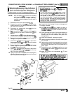
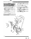
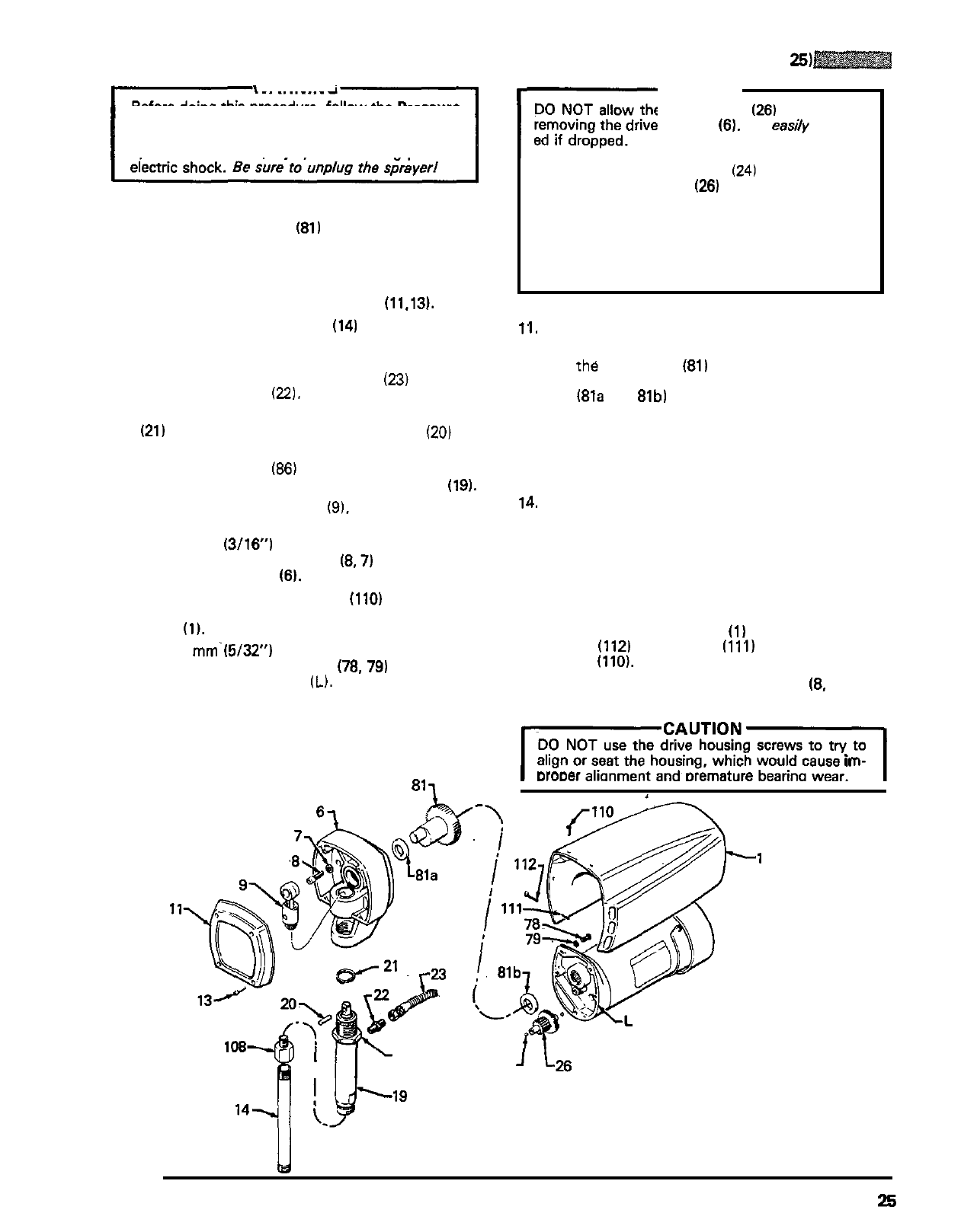
CONNECTING ROD, DRIVE HOUSING,
or
CRANKSHAFT REPLACEMENT
(See
Fig
25)
WARNING
Before doing
this
procedure, follow the Pressure
the risk of a fluid injection injury, splashing in the
Relief Procedure Warning on page
17
to reduce
eyes or on the skin, injury from moving parts or
NOTE:
Stop the sprayer at the bottom of its stroke
to get the crank
(81)
in
its lowest position. If
the crank must be lowered manually,
carefully rotate the blades of the fan with a
screwdriver.
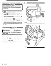
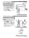
1.
Remove the front cover and screws
(11.13).
2.
Unscrew the suction tube
(14)
from the pump,
the pump from loosening.
holding a wrench on the pump intake valve to keep
3.
Disconnect the pump outlet hose
(23)
from the
pump outlet nipple
(22).
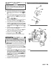
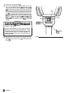
4.
Use
a screwdriver
to
push aside the retaining spring
(21)
at the top of the pump. Push the pin
(20)
out
the rear.
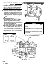
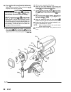
5.
Loosen the jam nut
(86)
with an adjustable wrench.
Unscrew and remove the displacement pump
(19).
6.
Remove the connecting rod
(9).
inspect for wear or
damage, and replace if needed.
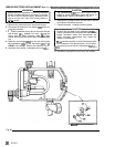
7.
Use a
5
mm
(3/16)
hex key wrench to remove the
three screws and lockwashers
(8.7)
from the recess
of the drive housing
(6).
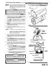
8.
Remove the four short screws
(110)
and
two
long
screws
(1121
and spacers
(1111
from the motor
shield
(1).
Remove the shield.
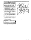
9.
Use a
4
mm.(5/32") hex key wrench to remove the
two
screws and lockwashers
(78, 79)
from the top
rear of the front end bell (L).
10.
Lightly tap the lower rear of the drive housing with
a plastic mallet
to
loosen
it
from the motor front end
bell. Then pull the housing
off.
811
r-
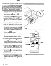
CAUTION
DO
NOT allow the gear cluster
(26)
to fall when
removing the drive housing
(6).
It
is
easiiy
damag
-
ed if dropped.
DO
NOT lose the thrust balls
(24)
located
at
each
end of the gear cluster
(26)
or allow them to fall
between gears. The ball, which is heavily covered
with grease, usually stays
in
the shaft recesses,
and not removed, the balls
will
seriously damage
but could be dislodged. If caught between gears
the drive housing. If the balls are not
in
place, the
bearings will wear prematurely.
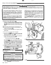
11.
Inspect the drive housing for wear or damage and
replace if needed.
12.
Pull the Crankshaft
(81)
out. Inspect for wear or
damage and replace, if needed. Be sure the bear
-
ings
i81a
and
81b)
are
in
place on either side of the
crankshaft assembly.
13.
Evenly lubricate the inside of the bronze bearing
in
the drive housing with high quality motor oil.
Liberally pack the roller bearings and gears
with
bearing grease.
14.
Install the crankshaft, meshing the gears.
15.
Clean the mating surfaces of the drive housing and
front end bell.
16.
Carefully align the drive housing and front end bell
with the locating pins, then push the drive housing
onto the front end bell or tap
it
into place with a
plastic mallet.
17.
Reinstall the motor shield
(1)
using the two long
screws
(112)
and spacers
(111)
and the four short
screws
(110).
18.
Install the screws and lockwashers
(8,
7)
and
tighten evenly.
ICAUTION1
DO
NOT use the drive housing screws to
try
to
align or seat the housing, which would cause
im-
DroDer alionment and Dremature bearina wear.
..
w
86
24
I
Fig
25
307
-
671
25