


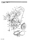
MOTOR
BRUSH
REPLACEMENT
(See Figs
27
8
28)
NOTE:
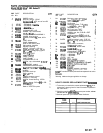
New motor brushes are included with each
11.
Reinstall the brush inspection covers, gaskets,
and
Packing Repair Kit. Replace them when screws. Reinstall the motor shield and screws.
replacing the packings, and/or when they
the longest side.
have been worn to a minimum of
9/16
on
Before doing this procedure, follow the Pressure
the risk of fluid injection injury, splashing
in
the
Relief Procedure Warning on page
17
to
reduce
eyes or on the skin, injury from moving parts or
electric shock.
Be sure
to
unplug the sprayer1
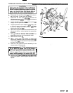
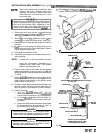
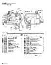
1.
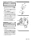
Remove the four short screws
(110)
and the
two
long screws (112) and spacers
(111)
from the motor
shield
(1).
Remove the shield. See Fig 27.
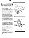
2. Remove the screws
(HI,
inspection covers
(JI
and
gaskets
(K) on each side of the motor. See Fig 27.
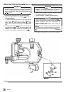
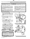
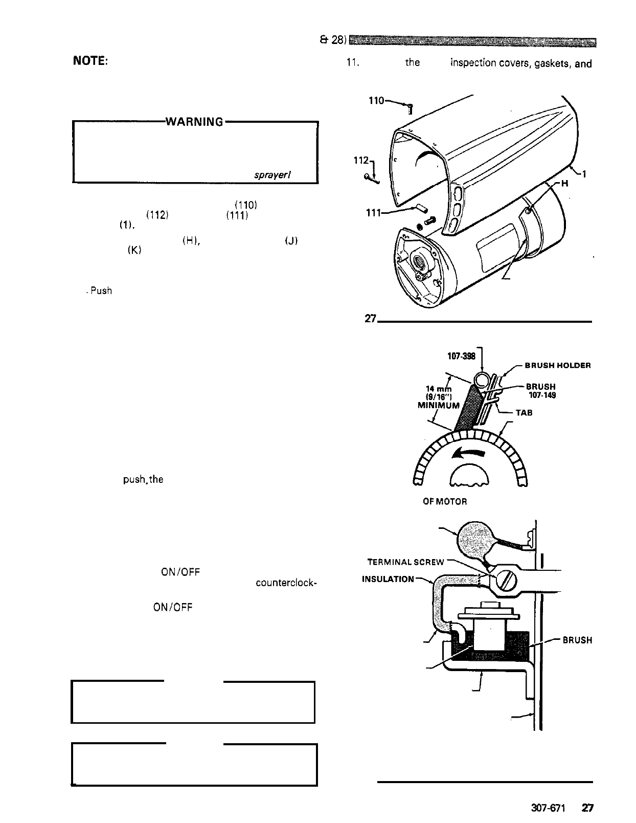
3.
Loosen
the brush lead terminal screw and remove
the lead.
4.
.Push down on the spring clip slightly then pull the
clip away from and out
of
the brush holder. Refer to
Fig 28. Keep the spring clip.
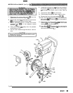
5.
Remove and discard the brush.
J.K
Fig
n
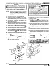
6.
Inspect the commutator for excessive pitting, burn
-
NOTE:
A black color on the commutator is normal.
ing or gouging.
SPRING CLIP
107-398
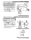
7.
8.
9.
Have the commutator resurfaced by a
qualified motor repair shop if the brushes
seem to be wearing too fast.
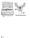
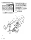
edges are as shown in the first part of Fig
28,
and
Place a new brush
in
the holder
so
the beveled
the brush lead is routed as shown
in
the second part
of Fig 28.
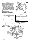
the brush holder until the clip tab engages in the
Slowly
push.the tabbed end of the spring clip into
holder
and
the rolled portion of the tension spring
rests squarely on the brush.
Route the brush lead to the terminal and tighten the
terminal screws. Be sure the brush lead does not
touch any part of the armature or motor housing.
COMMUTATOR COMMUTATOR
SIDEVIEW
OFMOTOR BRUSH INSTALLATION
CAPACITOR
I
10.
Test the brushes:
TERMINALSCREW
a.
With the ON/OFF switch OFF, turn the
pressure control knob all the way
counterclock-
wise to minimum pressure. Plug
in
the sprayer.
b. Turn the
ON/OFF switch ON and slowly
in
-
crease the pressure until the motor comes up to
full speed.
c.
Inspect the brush and commutator contact area
for excessive arcing. Arcs should not
"
trail
"
or
circle around the commutator surface.
WARNING
Do
not touch the brushes, leads, springs or brush
BRUSH HOLDER
holders while the sprayer is plugged in
to
avoid
electric shock and possible serious bodily injury.
MOTOR END BELL
BRUSH LEAD
SPRING CLIP
-BRUSH
Do
not run the sprayer dry for more than
30
CAUTION
seconds while checking the brushes to avoid
damaging the displacement pump.
Fig
28
SHOWN WITH MOTOR LEAD
DETAIL OF MOTOR BRUSH
FACING BACK OF MOTOR
~
307-671
27