


GENERAL
REPAIR
NOTES
WARNING
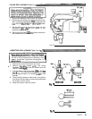
Pressure Relief Procedure
To'reduce the risk of serious bodily injury,
in
-
cluding fluid injection, splashing fluid in the eyes
or on the skin, or injury from moving parts or elec
-
tric shock, always follow this procedure whenever
you shut
off
the sprayer, when checking or servic:
ing any part of the spray system, when installing,
cleaning or changing spray tips, and whenever
you stop spraying.
1 .Engage the gun safety latch.
2 .Turn the
ONIOFF switch to OFF.
3
.Unplug the power supply cord.
4 .Disengage the gun safety latch.
5
.Hold
a
metal part of the gun firmly to the side of
a grounded metal pail, and trigger the
gun
to
relieve pressure.
6
.Engage the gun safe& latch.
7 .Open the drain valve, having a container ready
8
.Leave the drain valve open until you are ready
If
you suspect that the spray
tip
or hose
is
com
-
pletely clogged, or that pressure has not been fully
relieved after following the steps above, VERY
SLOWLY loosen the tip guard retaining nut or
hose end coupling and relieve pressure gradually,
then loosen completely. Now clear the
tip
or hose.
to catch the drainage.
to spray again.
Tool
List
The following tools are needed when repairing this
sprayer.
Phillips screwdriver
Small flatblade screwdriver
Needle nose pliers
Plastic mallet
Adjustable wrench
2
"
adjustable, open
-
end wrench
Torque wrench
114"
hex key wrench
3/16
"
hex key wrench
518"
socket wrench
318"
open end wrench
314"
open
end wrench
112''
open
end wrench
718"
open end wrench
High quality motor oil
Bearing grease
318
ignition wrench
For calibration procedure only:
0.015'
spray tip
High pressure, oil
-
filled test gauge, Part No. 102-814
5
gallon pail
Clean water
Mineral spirits
NEW
207
bar
(3oM)
psi) high pressure spray hose,
Part
No.
214-915.
ing
general repair notes and the repair procedure. Be
Before repairing any part of the sprayer, read the
follow-
sure you have the necessary tools and parts available.
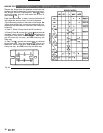
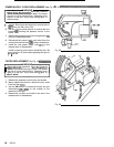
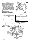
1.
When disconnecting wires
in
the pressure control
assembly, use needle nose pliers to separate mating
connectors.
When reconnecting the wires, be sure the flat blade
wrap
-
around blade of the female connector when
of the insulated male connector is centered
in
the
the connection is made.
CAUTION
tion, be sure to properly mate connectors, and
never pull on a wire to disconnect
it.
Pulling on a
wire could loosen the connector from the wire.
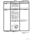
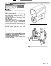
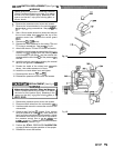
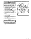
2.
Route wires in the pressure control assembly
carefully through the legs of the U
-
shaped bourdon
tube, where appropriate, to avoid interfering with
the bourdon tube which moves as the pressure set
-
ting changes and to avoid pinching the wires be
-
tween the pressure control box and cover.
CAUTION
Improper wire routing can result
in
poor sprayer
performance or damage to the pressure control.
3.
Keep
all
screws, nuts, washers, gaskets, and elec
-
trical fittings removed during repair procedures.
These parts are not normally provided with replace
-
ment assemblies.
4.
Test your repair before regular operation of the
sprayer to be sure the problem is corrected.
If the sprayer does not operate properly, review the
repair procedure again to verify that everything was
done correctly. If necessary, refer to the
Troubleshooting Guide, pages
9
-
16,
to help identify
other possible problems and solutions.
FWARNlNGl
To reduce the risk of serious bodily injury, in
-
cluding electric shock, DO NOT touch any moving
while
inspecting.the repair.
parts or electrical parts with your fingers or a tool
complete the inspection.
Shut
off
the sprayer and unplug
it
as soon as you
before operating the sprayer.
Reinstall all covers, gaskets, screws and washers
CAUTION
seconds to avoid damaging the pump packings.
Do not run the sprayer dry for more than
30
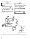
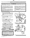
5.
Reinstall the motor cover before regular operation
of the sprayer and replace
it
if
it
is damaged. The
cover directs cooling air around the motor to help
prevent overheating.
It
can also help prevent burns,
fire or explosion; see the WARNING, below.
WARNING
and could burn your skin if touched. Flammable
During operation, the motor becomes very hot
materials spilled on the hot, bare motor could
cause a fire or explosion. Always have the motor
cover in place during regular operation to reduce
the risk of burns, fire or explosion.
307-671
17