


~~
TYPE
OF
PROBLEM
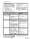
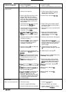
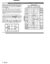
LOW OUTPUT
NO OUTPUT
Motor runs and pump stroke:
307-671
WHAT
TO
CHECK
If
check is
OK.
go to next check
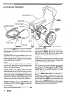
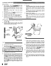
1. Check for worn spray tip.
2. Check
to
see
that
pump does not con
-
tinue
to
stroke when gun trigger is
released. Plug in and turn on sprayer.
Prime with paint. Trigger gun momen
-
tarily, then release and engage safety
latch. Relieve pressure, turn
off
and
unplug sprayer.
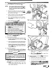
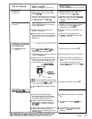
3. Check electrical supply with volt meter.
Meter should read
190-250
Volts.
4. Check extension cord size and length;
must be at least 12 gauge wire and no
longer than 15.2 m
(150
ft).
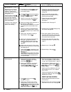
5.
Check G1 and G2 leads from bridge
or loose wires or connectors. Refer
to
WX)
to
circuit board
1340)
for damage
page
22.
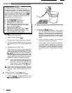
6.
Check stall pressure. Refer
to
Calibration
Procedure on page 24.
7.
Check bridge
(308)
+
and
-
leads and
terminals
to
motor. Inspect
wiring
in
-
sulation and terminals for signs of
overheating. See page
20.
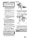
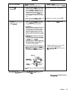
8.
Check for loose motor brush leads and
terminals. See page
27.
9.
Check for worn motor brushes which
should be 14 mm
(9/16) minimum. See
pBge
27.
10.Check for broken and misaligned motor
brush springs. Rolled portion of spring
must rest squarely on top of brush.
11.Check motor brushes for binding
in
brush holders. See page 27.
12.Check circuit board
1340)
by substituting
with a good circuit board. See page
22.
13.Check motor armature for shorn by us
-
ing an armature tester (growler) or per
-
form spin
test.
See
page 15.
14.Check bridge
(308)
by substituting with
a good bridge or by performing the
bridge test. See page 16 or
20.
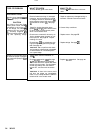
CAUTION:
Do
not perform this check
A bad armature
will
immediately burn
until armature is determined
to
be good.
out
a
good bridge.
1.
Check paint supply.
2. Check for clogged intake strainer.
3. Check for loose suction tube or fittings.
WHAT
TO
DO
If
check
is
NOT
OK
refer to this column
1. Follow Pressure Relief Procedure
Warning then replace
tip.
See your
separate gun or tip manual.
2.
Service pump. See manual 307-793.
3. Reset building circuit breaker; replace
building fuse. Repair electrical outlet or
try
another outlet.
4. Replace with a correct, grounded exten
-
sion cord.
5.
Clean circuit board male terminals.
minals. Securely reconnect lead
ter-
Replace loose or defective lead ter
-
minals to board.
6.
Calibrate pressure control. See page 24.
7. Be sure male terminal
blades are
centered and firmly connected to female
terminals. Replace any loose terminal or
damaged wiring. Securely reconnect
wires to bridge.
8.
Tighten terminal screws. Replace
brushes if leads are damaged. See page
27.
9.
Replace brushes. See page
27.
10.Replace spring if broken. Realign spring
with brush. See page
27.
11 .Clean brush holders, remove carbon
dust with small cleaning brush. Align
brush lead with
slot
in brush holder
to
assure free vertical brush movement.
12.Replace circuit board. See page
22.
13.Replace motor.
See
page
29.
14.Repiace bridge. See page
20.
1. Refill and reprime pump.
2.
Remove and clean, then reinstall.
3. Tighten; use thread sealant or sealing
tape on threads if
necessary.