


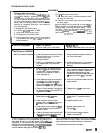
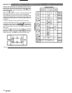
YPE
OF
PROBLEM
Condition
B
(continued)
Condition
C
Red
lamp on, clear lamp
off
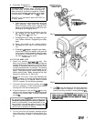
Unplug
sprayer1
WHAT TO CHECK
f
check is
OK,
go
to
next
check
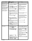
i.
Check microswitch
1306).
With no fluid
pressure in the pressure control discon
-
nect wires TP18 and TP19. Check con
-
tinuity across switch terminals with an
ohmmeter. Switch contact should be
closed. Depress actuator
bunon. An
audible
"click" indicates the contacts
have opened. Ohmmeter should read in
-
finity.
i.
Check circuit board
(3401
by substituting
with a good board. See page
22.
.
Check circuit board
(3401
by removing
from box
wirhout
disconnecting wires;
sea
page
22
for removal procedure.
WARNING:
Removing the circuit board
while still wired over
-
rides the optical
.
to over
-
pressurize, if the microswitch
detector which could cause the sprayer
does not function properly. Tum the
sprayer on
ONLY
long enough to check
lamp condition, then shut
off
immediate
-
ly.
WARNING:
To reduce the risk of elec
-
tric shock, handle board by edges only1
Do
not allow any metal objects to come
in
contacl with the boardl
should be
on
now
-
removing the circuit
Plug in and turn on sprayer. Clear lamp
board over
-
rides the optical detector.
Turn
off
and unplug sprayer.
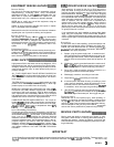
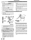
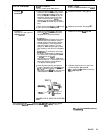
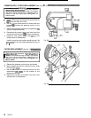
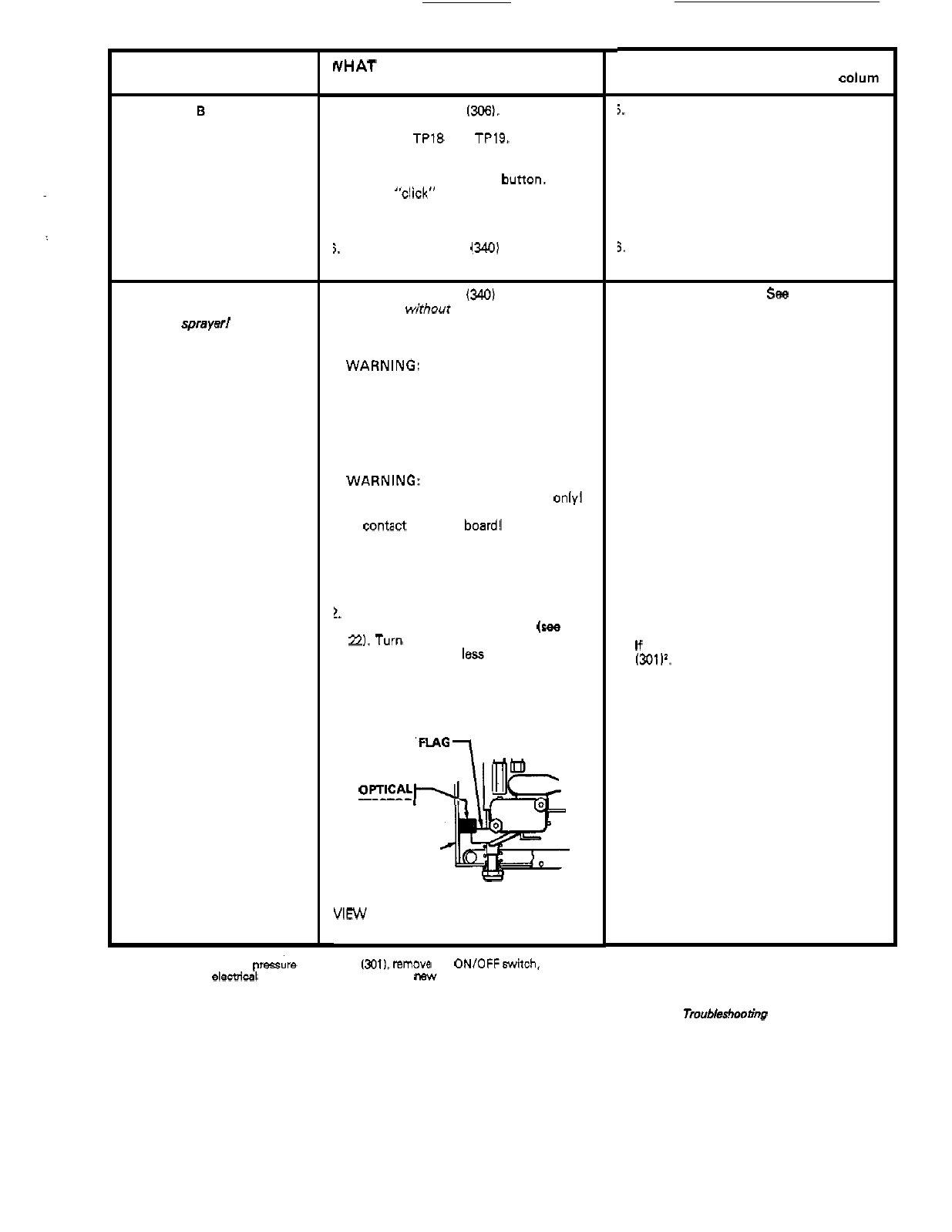
!.
Check bourdon tube flag and detector
position. Reinstall circuit board
(see
page
22.
Turn pressure setting to maximum;
flag should extend
less
than half way into
optical detector slot from the bonom.
DETECTOR
C
I
R
C
U
I
T
-
BOARD
VIEW
OF
OPTICAL DETECTOR AND
FLAG
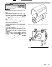
'When replacing
the
bare pressire control box 13011.
remow
the
ON/OFFswitch,
bridge,
circuit
board
and
elecbical
hardware and
reinstall
in
the
new bare box.
WHAT TO
DO
If
check
is
NOT
OK
refer
to
this colurn
5.
Replace microswitch. See page 19.
3,
Replace circuit board. See page
22.
I.
Replace circuit board.
Sea
page
22.
2.
Calibrate pressure control to
sea
if
that
corrects problem.
See
page
24.
If
not, replace bare pressure control box
13011'.
See
page
23.
Tmubleshooting continued on next
page.
307
-
671
11