


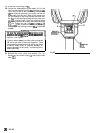
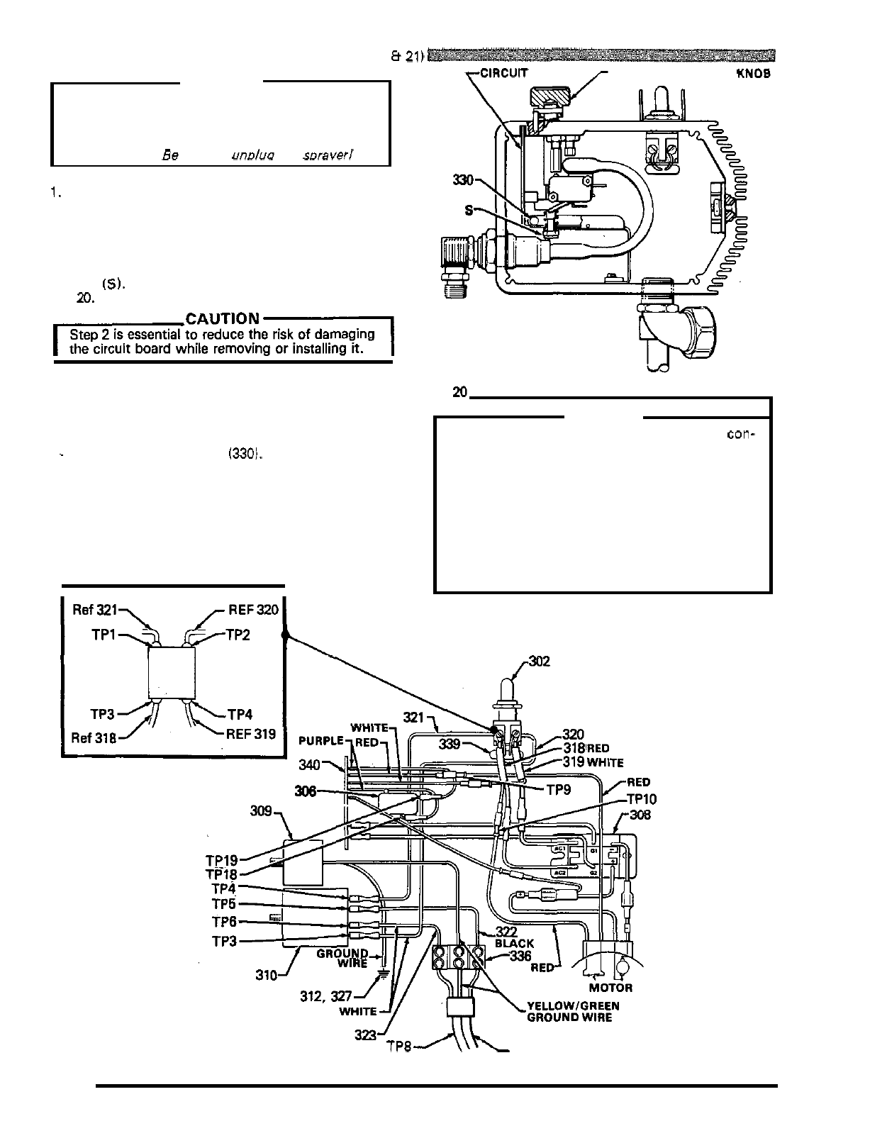
CIRCUIT BOARD REPLACEMENT
(See
Figs
20
8
21)
WARNING
Before doing this procedure, follow the Pressure
the risk of a fluid injection injury, splashing
in
the
Relief Procedure Warning on page
17
to reduce
eyes or on the skin, injury from moving parts, or
electric shock.
Be sure
to
unolua
rhe soraverl
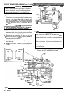
rClRCUlT
BOARD
r
PRESSURE CONTROL
KNOB
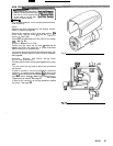
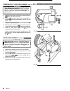
1.
Remove the pressure control cover and screws.
2.
Turn the pressure control knob all the way counter
-
clockwise to the minimum setting to release spring
tension on the board.
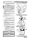
Also
check to be sure only
three or four threads
of
the pressure control knob
shaft are exposed below the pressure adjustment
nut
(SI.
Back down the nut, if necessary.
See
Fig
20.
IcAuTloNl
Step
2
is essential to reduce the risk of damaging
the circuit board while removing
or
installing
it.
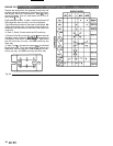
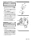
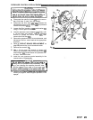
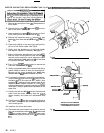
3.
Disconnect
ALL
wires from the board, including the
two
heavy black wires. Pay close attention
to
where
connections are made.
See
Fig
21.
.
4. To
remove the board from the box, pull out the
-
black plastic
-
tipped pin
(330).
Push the
bottom
of
the circuit board toward the wall of the box and
carefully slide the board out.
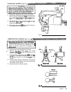
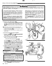
5.
Install the board
in
the box at the Same angle as
it
was removed.
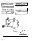
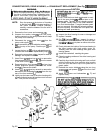
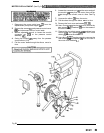
6.
Reconnect all wires. Refer to the wiring diagram
in
Fig
21.
Fig
P
CAUTION
nector is centered exactly
in
the wrap
-
around
Be sure the flat blade of the insulated male con-
blade of the female connector when connections
are made.
Route all wires carefully to avoid interference
with
the circuit board, bourdon tube and pressure con
-
trol cover.
These precautions are essential to reduce the risk
of malfunction.
7.
Perform the
STALL
PRESSURE
CALIBRATION
on page
24
if you installed a new board.
TP8
TP7
Fig
21
PLUQ
22
307
-
671