


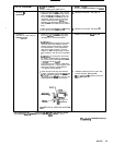
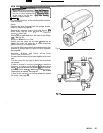
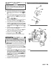
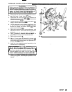
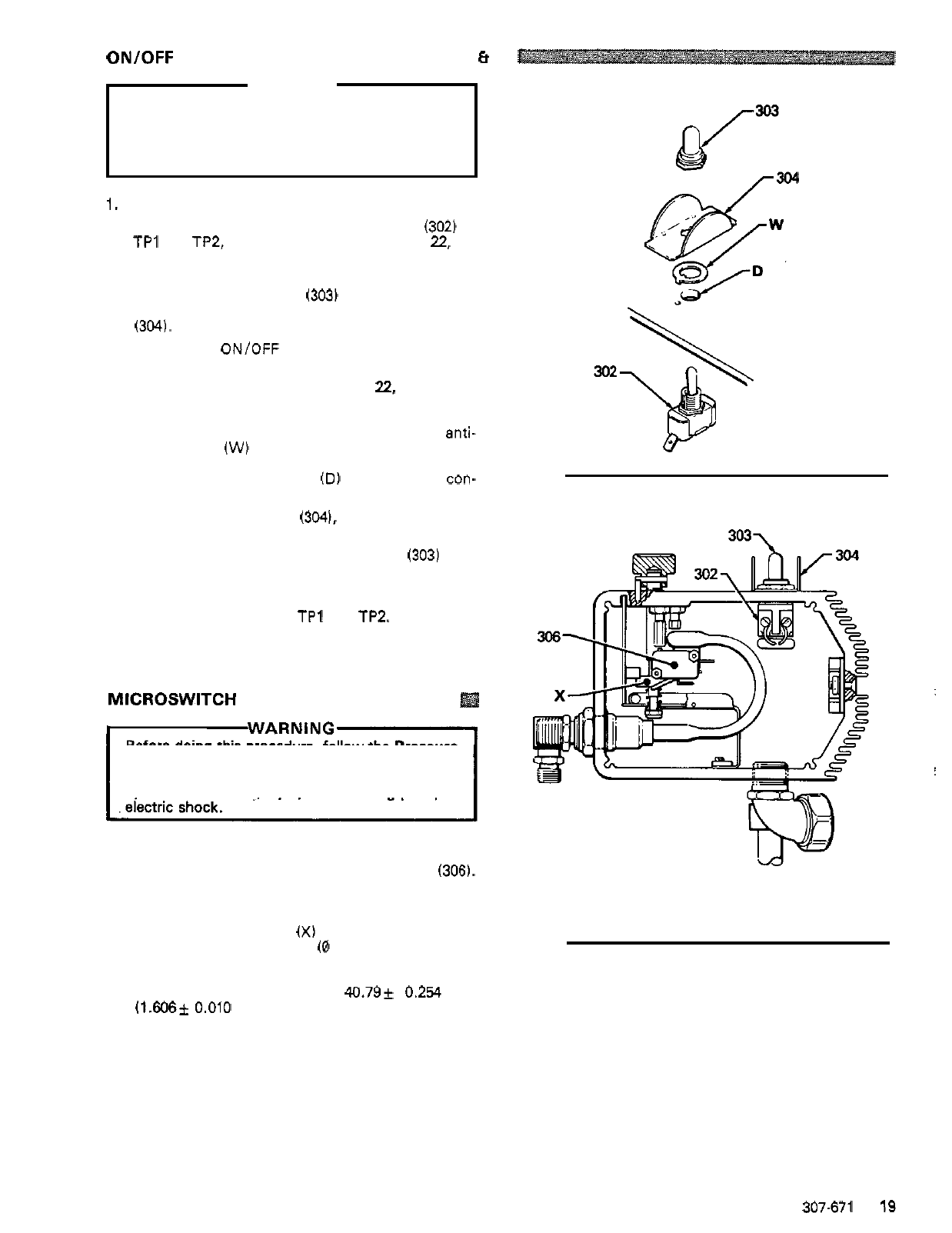
ON/OFF SWITCH REPLACEMENT
(See Figs 14
Et
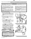
WARNING
Before doing this procedure, follow the Pressure
Relief Procedure Warning on page 17 to reduce
the risk of
a
fluid injection injury, splashing
in
the
eyes or on the skin, injury from moving parts, or
electric
shock.
1. Remove the pressure control cover and screws.
2. Remove the wires attached to the switch
(302) at
TPl and TP2, using a screwdriver. See page
22,
Fig
21.
3.
Use a 16 mm socket wrench to loosen and remove
the nut and rubber boot
(303)
from the top of the
pressure control box. Remove the switch guard
(304).
4. Remove the ONIOFF switch.
5. Remove the wires attached to the switch TP4 and
TP3 using a screwdriver. See page
22,
Fig 21.
6. Attach the wires to TP4 and TP3 of the new switch.
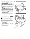
7. Install the new switch
so
the internal tab of the anti-
rotation ring
(W)
engages with the vertical groove
engages
with
the blind hole
(D)
of the pressure con-
in
the threads of the switch, and the external tab
trol box.
8.
Install the switch guard (304). aligning the internal
tab with the groove
in
the threads.
9. Powder the inside of the rubber boot
(303)
with
talcum, then shake excess out of boot.
10. Install the nut and rubber boot and tighten.
11. Reconnect the wires to
TP1 and TP2.
12. Reinstall the pressure control cover and screws.
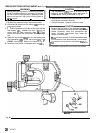
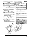
MICROSWITCH REPLACEMENT
(See Fig 15)
Before doing this procedure, follow the Pressure
the risk of a fluid injection injury, splashing
in
the
Relief Procedure Warning on page 17 to reduce
eyes or on the skin, injury from moving parts, or
1. Remove the pressure control cover and screws.
2. Disconnect both wires from the microswitch
(3061.
3. Use the socket wrench to remove the nuts from the
microswitch.
4. Check to see if the flag
(X)
is loose. If
it
is, be sure
the
fluid
pressure is
0
bar
(0
psi), then loosen the
two
6
mm hex nuts behind the microswitch. Adjust
the distance from the top of the flat to top inside
of
the pressure control box to 40.79k 0.254 mm
(1.606*
0.010
in.).
Tighten the screwsand recheck
the dimension. Refer to Fig 1.
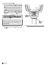
5. Perform the
STALL
PRESSURE
CALIBRATION
on page 24 before regular operation of the sprayer.
6. Reinstall the cover
and
screws.
15)
Fig
14
Fig
15
307-671
19