


Model G0773 (Mfd. Since 12/14)
-23-
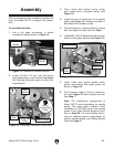
With the exception of the handwheel handles and
belts, the Model G0773 is shipped fully assem-
bled.
Assembly
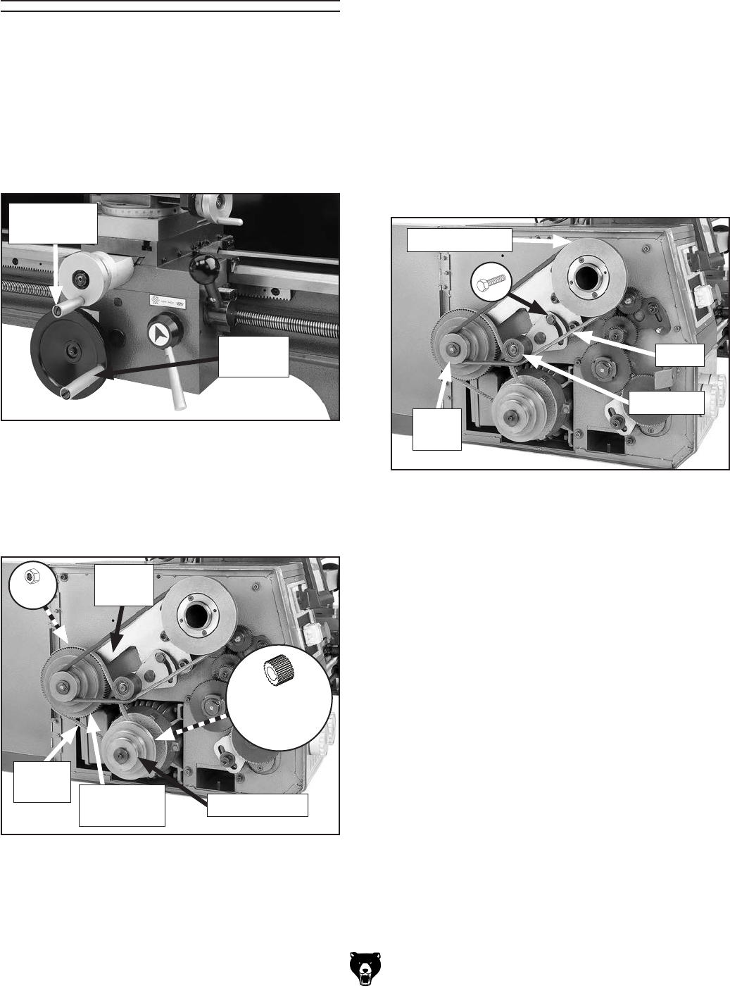
3. Place timing belt behind motor pulley
and around motor timing-belt pulley (see
Figure 15).
2. Loosen (2) M12-1.75 hex nuts that secure
timing-belt pulley to idler bracket (see Figure
15), allowing timing-belt pulley to slide in its
mounting slot.
Motor
Timing-Belt
Pulley
x2
Figure 15. Timing belt installation components.
Motor Pulleys
Timing
Belt
Timing-Belt
Pulley
Idler
Bracket
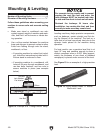
Figure 14. Handwheel handles installed.
Carriage
Handle
Cross Slide
Handle
To assemble machine:
1. Use a flat head screwdriver to attach
handwheel handles shown in Figure 14.
4. Install free end of timing belt on timing-belt
pulley (see Figure 15), making sure teeth of
belt mesh with notches in pulley.
5. Pull timing-belt up, creating tension in timing
belt, then tighten (2) hex nuts from Step 1.
6. Loosen M8-1.25 x 25 hex bolt that secures ten-
sioner to timing gear bracket (see Figure 16).
Tensioner
7. Install V-belt onto largest spindle pulley
groove and smallest idler pulley groove, as
shown in Figure 16.
8. Pivot tensioner against V-belt to create ten-
sion (see Figure 16) and re-tighten hex bolt
from Step 1.
Figure 16. V-belt controls and components.
V-Belt
Spindle Pulley
Idler
Pulley
Note: The V-belt/pulley configuration of
Model G0773 varies depending on spindle
speed. The steps above illustrate V-belt
installation for 150 RPM, which is the starting
speed in the Lathe Spindle Break-In proce-
dure on Page 26. For more detailed instruc-
tions on selecting proper configurations for
specific spindle speeds, see Setting Spindle
Speed on Page 41.