Model G0773 (Mfd. Since 12/14)
-43-
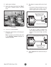
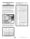
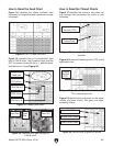
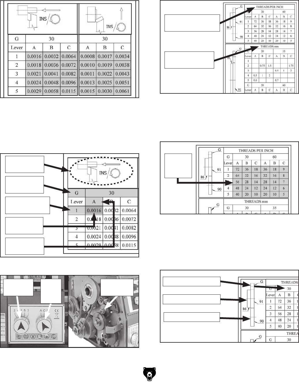
Figure 54 identifies the fifteen available feed
rates each for longitudinal and transverse carriage
movement.
How to Read the Feed Chart
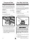
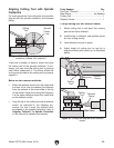
Figure 59 identifies the end gears on the upper,
middle, and lower shafts. The gears are repre-
sented by letters.
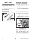
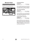
Figure 57 identifies the charts to use when set-
ting carriage feed movement for metric or inch
threading.
Figure 57. Headings indicate inch or metric
threads.
How to Read the Thread Charts
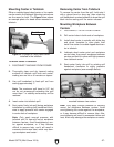
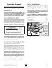
Figure 58 shows the threads per inch (TPI) on the
applicable chart.
Figure 58. Numbers in dotted line indicate the
TPI or threads per inch.
Threads
Per Inch
(TPI)
Figure 59. Identification of gears on shafts.
Upper Shaft Gears
Middle Shaft Gears
Lower Shaft Gears
Figure 54. G0773 feed rate chart.
Indicates Metric
Thread Pitch
Indicates Threads
Per Inch (TPI)
Figure 55 indicates that for a longitudinal feed
rate of 0.0016 in/rev., the G position gear must be
30T, the numeric feed dial set to 1, and the alpha
feed dial set to A (see Figure 56).
Longitudinal
Feed Icon
30T Gear in
G Position
Alpha Feed
Dial Set to A
Numeric Feed
Dial Set to 1
Feed Rate
.0016 in/rev.
Figure 55. Reading feed chart.
Figure 56. Feed dial and gear settings for
0.0016 in/rev.
Numeric
Feed Dial
Alpha
Feed
Dial
G Position
Gear 30T


