


-52-
Model G0773 (Mfd. Since 12/14)
Removing
Compound Rest
The compound rest and tool post must be removed
before milling operations so the cross-slide table
can be used as the milling table.
Tools Needed Qty
Hex Wrench 3mm .............................................. 1
Hex Wrench 4mm .............................................. 1
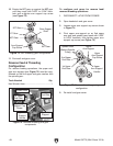
Removing Compound Rest
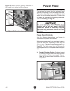
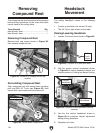
Remove both cap screws shown in Figure 82,
then remove compound rest.
Figure 82. Location of compound rest cap
screws.
x 2
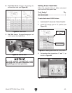
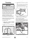
Re-installing Compound Rest
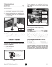
Align compound rest with swivel base mounting
post and M8-1.25 T-nuts (see Figure 83), then
secure with cap screws previously removed.
Figure 83. Swivel base components.
Mounting Post
x2
Headstock
Movement
The milling headstock moves in the following
ways:
• Travels up and down the column (Z-axis).
• Tilts 45° left or right relative to the table.
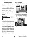
Raising/Lowering Headstock
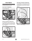
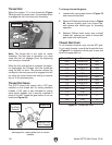
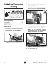
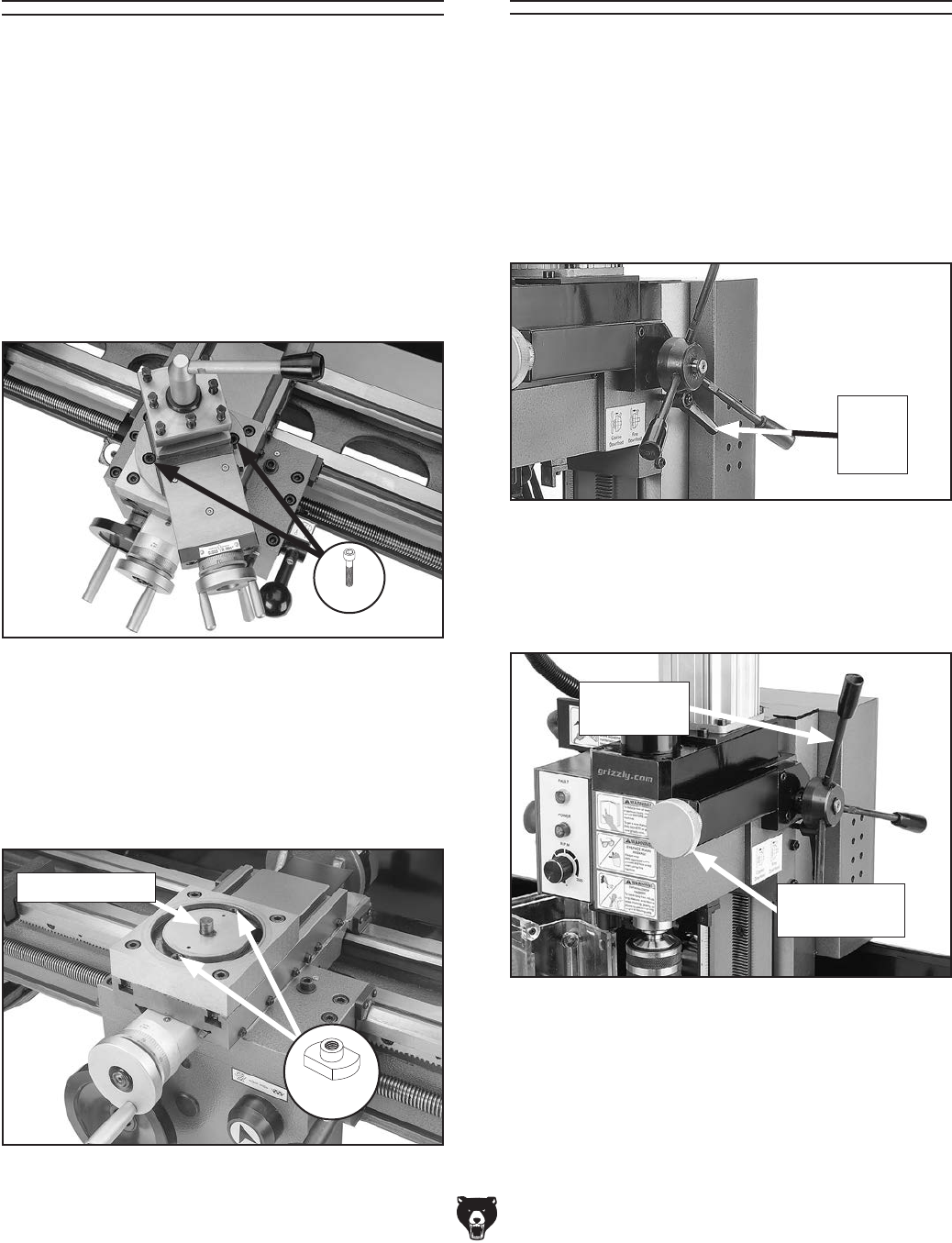
1. Loosen Z-axis lock lever shown in Figure 84.
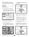
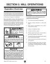
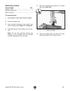
3. Use the fine vertical handwheel shown in
Figure 85 for precision vertical adjustment
during milling operations.
4. Retighten lock lever.
Figure 84. Location of Z-axis lock lever.
Z-Axis
Lock
Lever
2. Use the coarse vertical handwheel shown
in Figure 85 to adjust headstock height and
relative position of cutting tool before cutting.
Figure 85. Location of mill headstock vertical
controls.
Vertical
Handwheel
Fine Vertical
Handwheel