Model G0773 (Mfd. Since 12/14)
-49-
Threading
The following subsections will describe how to
use the threading controls and charts to set up the
lathe for a threading operation. If you are unfamil-
iar with the process of cutting threads on a lathe,
we strongly recommend that you read books,
review industry trade magazines, or get formal
training before attempting any threading projects.
Headstock Threading Controls
The threading charts on the headstock face dis-
play the settings for inch and metric threading.
Using the controls on the lathe, follow the exam-
ple below to understand how to set up the lathe
for the desired threading operation.
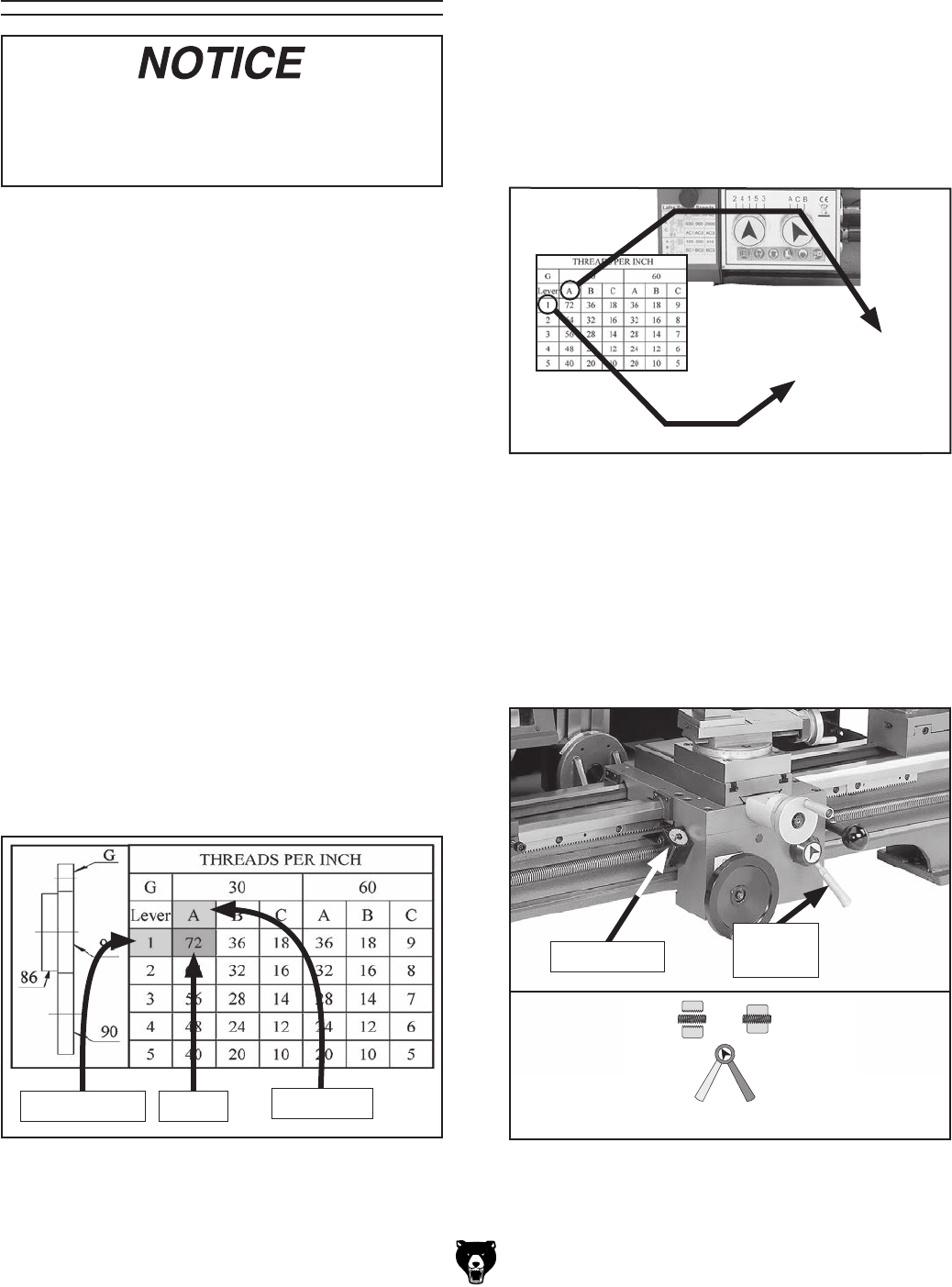
To set dials for 72 TPI:
1. Arrange gears in Primary Threading
Configuration, with 30T gear in "G" position,
as explained on Page 46.
2. Locate 72 TPI on the inch threading chart
below.
Figure 76. 72 TPI and corresponding dial
positions.
72 TPI
Alpha Dial
Numeric Dial
Figure 77. Gearbox dial settings for 72 TPI.
3. Locate A above 72 TPI and find 1 to the left
of it.
Note: In the next step, use the chuck key to
rock the spindle back-and-forth to help mesh
the gears as you make adjustments.
4. Position gearbox dials, as shown in Figure
77.
The lathe is now setup to cut 72 TPI threads.
Apron Threading Controls
Figure 78. Apron threading controls.
Half Nut
Lever
Thread Dial
The half nut lever engages the carriage with the
leadscrew, which moves the carriage and cutting
tool along the length of the workpiece for thread-
ing operations (see Figure 78).
Engaged Disengaged
When threading, use slowest speed pos-
sible and avoid deep cuts, so you are able to
disengage half nut when required to prevent
a carriage crash!


