


-28-
Model G0773 (Mfd. Since 12/14)
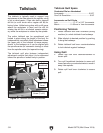
Chuck Mounting
This lathe ships with the 3-jaw chuck installed.
This is a scroll-type chuck where all three jaws
move in unison when the chuck key is used.
The included 4-jaw chuck features independent
jaws, which are used for square or unevenly-
shaped stock, and to mount work that needs to be
adjusted to near zero total indicated runout.
The included faceplate has slots for T-bolts that
hold standard or custom clamping hardware. With
the correct clamping hardware, a faceplate offers
a wide range of uses, including machining non-
concentric workpieces, straight turning between
centers, off-center turning, and boring.
Never use spindle speeds faster than chuck
RPM rating or safe limits of your workpiece.
Excessive spindle speeds greatly increase
risk of workpiece or chuck being thrown
from machine with deadly force!
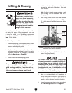
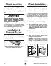
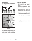
Installation &
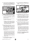
Removal Device
Figure 21. Example of common device used
during chuck installation and removal.
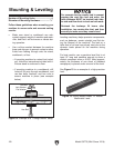
Plywood Protection
Plate for Chucks
Installed by Hand
Place a piece of plywood over the bedways to pro-
tect them from damage if a chuck or other tooling
is dropped (see below).
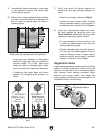
This lathe is equipped with a D1-type spindle
nose. This type of spindle uses camlocks that are
adjusted with a chuck key to securely mount a
chuck or faceplate with repeatable precision and
ease.
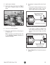
Chuck Installation
To ensure accurate work, it is extremely important
to make sure the spindle nose and chuck mating
surfaces/tapers are clean. Even a small amount of
lint or debris can affect accuracy.
The chuck is properly installed when all camlocks
are tight, the spindle and chuck tapers firmly
lock together, and the back of the chuck is firmly
seated against the face of the spindle all the way
around—without any gaps.
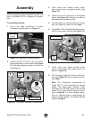
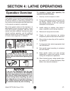
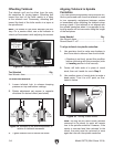
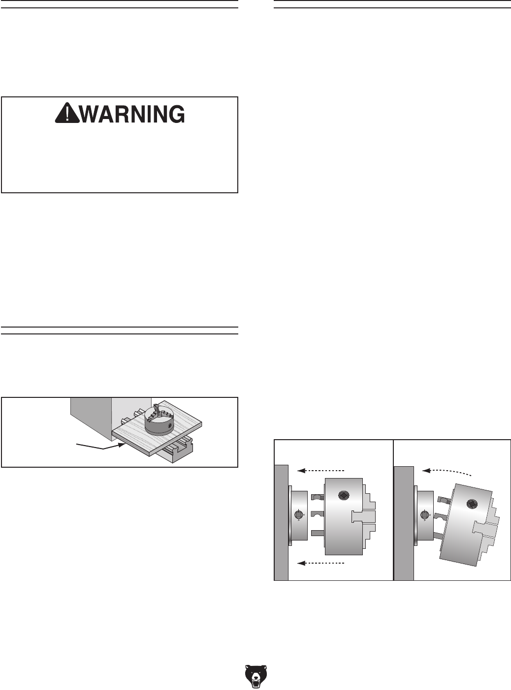
Figure 22. Inserting camlock studs into spindle
cam holes.
INCORRECTCORRECT
To install chuck:
1.
DISCONNECT LATHE FROM POWER!
2.
Use appropriate lifting, support, or protec-
tive device to protect ways and support
chuck during installation process (refer to
Installation & Removal Devices
section on
previous page).
3.
Clean and lightly oil camlock studs, then thor-
oughly clean mating surfaces of spindle and
chuck.
4.
Install chuck by inserting camlock studs
straight into spindle cam holes.
Important:
Avoid inserting the studs by piv-
oting them in from an angle or rotating the
spindle. This can damage studs or spindle
cam holes.