


-24- G0501 Sliding Table Saw
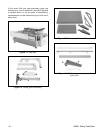
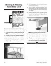
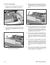
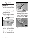
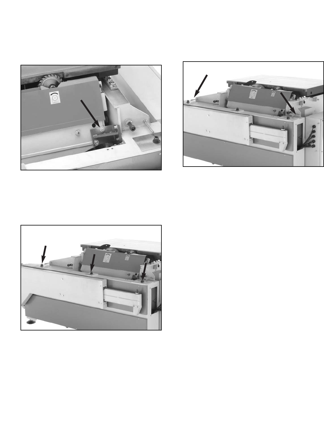
Figure 25. Three large caps screws to be
removed from saw base unit.
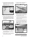
Figure 24. Blade tilt shipping brace.
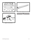
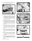
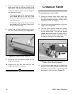
Figure 26. Parallel adjustment bolts.
To install the sliding table:
1. Remove the red shipping brace, shown in
Figure 24, from the blade tilt mechanism.
3. Back out the parallel adjustment bolts shown
in Figure 26, but do not completely remove
them or the jam nuts that are installed on
them.
2. Using a 12mm hex wrench, remove the three
large cap screws (Figure 25) from the saw
base unit.
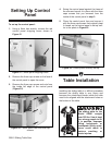
4. While the sliding table is still in its crate, pen-
cil a light mark on the front of the table that
references the middle mounting hole. Note—
This step will save time when positioning the
sliding table on the base unit.
5. Now, locate the middle attachment hole on
the base unit (where you removed the large
cap screws in step 2) and pencil a light align-
ment mark on the front of the machine base
unit.
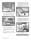
6. Use at least four strong people to lift the slid-
ing table onto the base unit. The edge of the
sliding table should be up against the edge of
the base unit table and the penciled refer-
ence marks should be aligned with each
other.
7. Have two of your assistants hold the sliding
table in position so that it does not fall while
you are securing it to the base unit.