


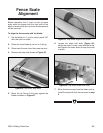
G0501 Sliding Table Saw -31-
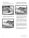
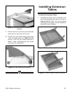
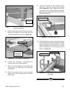
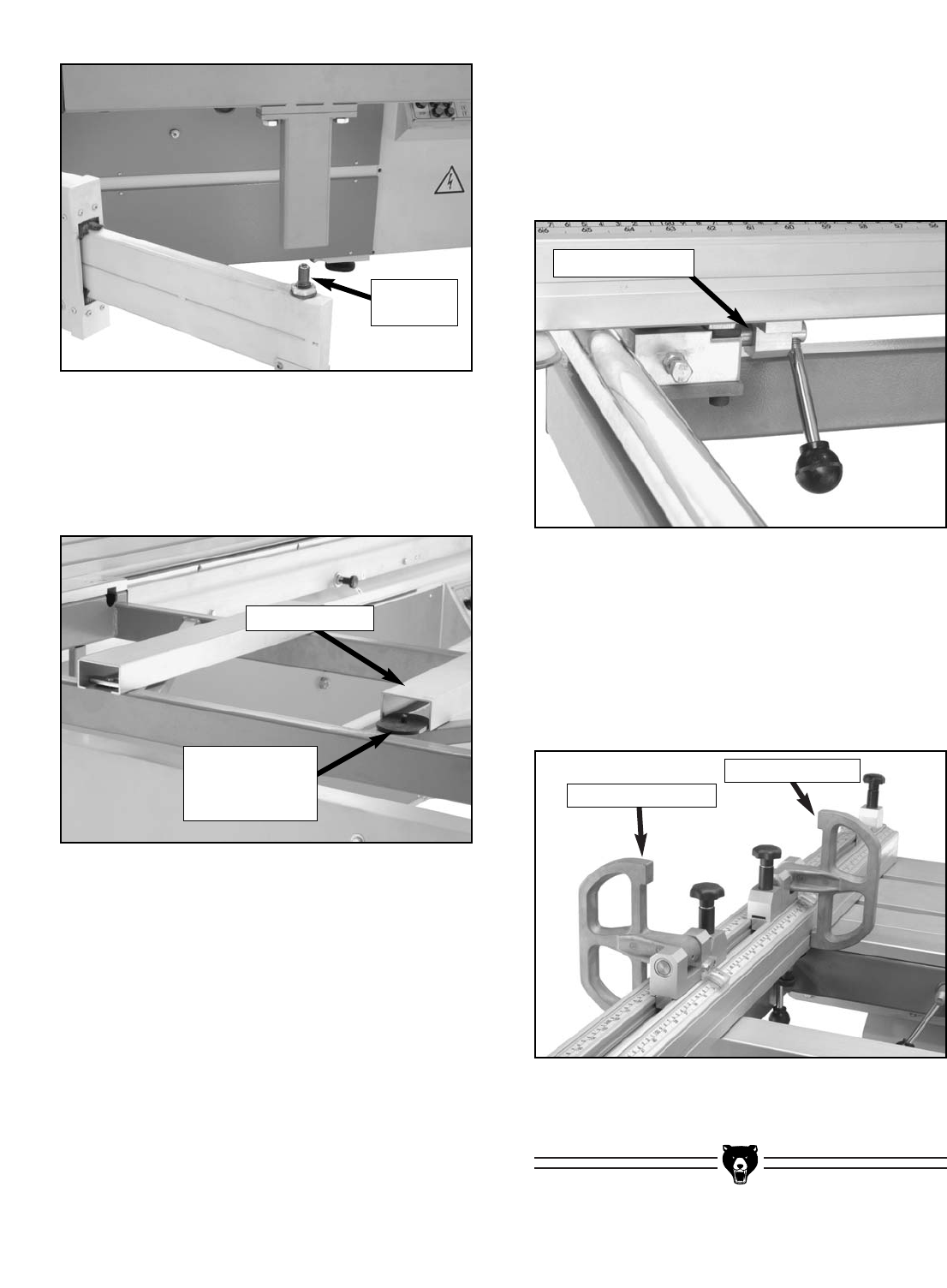
Figure 47. Mounting the crosscut table over the
shaft on the brace.
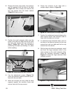
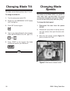
Figure 48. Cross-support assemblies.
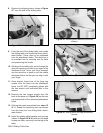
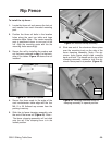
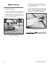
Figure 49. Cam lock rod (1 of 2).
5. Remove both end caps from the short cross-
support and remove one end cap from the
long cross-support as shown in Figure 48.
9. Using the handles on the crosscut fence,
slide the 2 cam lock rods into the crosscut
table (Figure 49). Note—Make sure the lock-
ing bolts on the crosscut fence are disen-
gaged so the locating pins will easily fall into
the table extension.
6. Loosen the hold-down assemblies that
secure each of the cross-supports.
7. Slide the cross-supports into position and
secure them by tightening the hold-down
assemblies.
8. Place the crosscut fence on the crosscut
table so that the locating pins fit inside the
guide holes.
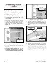
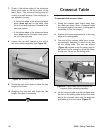
10. Install the flip stop units in the crosscut fence
by unlocking the extension piece and align-
ing the clamp bar on the bottom of the flip
stop unit to slide it into the fence. The correct
order of placement for the flip stop units is
shown in Figure 50.
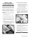
Figure 50. Correct order of flip stop unit
placement.
Inside Flip Stop
Outside Flip Stop
Mounting
Shaft
Cam Lock Rod
Cross-support
Hold-Down
Assembly
Cross-support