


G0501 Sliding Table Saw -29-
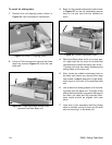
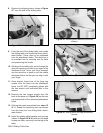
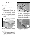
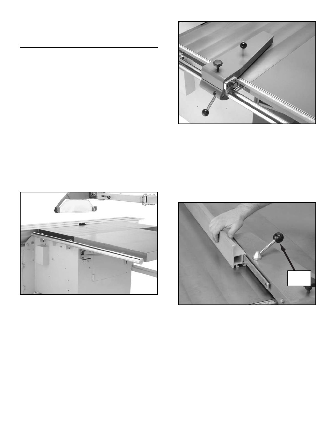
6. Slide one end of the aluminum fence piece
over the mounting track on the side of the
fence clamping assembly. Note—The alu-
minum fence piece should slide smoothly
back and forth. The handle on the top of the
clamping assembly rotates to lock the alu-
minum fence piece into position (Figure 44).
Figure 44. Installing aluminum fence to
clamping assembly in upward position.
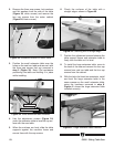
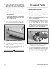
Figure 43. Installed clamp assembly.
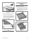
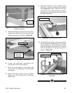
Figure 42. Fence rail installed.
Rip Fence
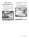
4. Secure the fence scale to the edge of the
cast iron/extension table edge with the four
M6-1.0 x 30 flathead cap screws from the
packing inventory.
5. Slide the rip fence clamping assembly onto
the end of the fence rail (Figure 43). Note—
The fence clamping assembly will not slide
onto the rail if the clamping lever is in the
locked position.
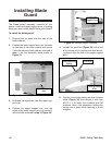
To install the rip fence:
1. Locate the fence rail and remove the last nut
and washer from each threaded mounting
post.
2. Position the three rail bolts in the location
holes along the cast iron table and large
extension table. Note—The center mounting
post is positioned closer to one end of the
rail. Align the mounting posts with the the
mounting holes accordingly.
3. Secure the rail by installing the washer and
nut that were removed in step 1 to the back-
side of the tables. Figure 42 shows the rail
installed.
Lock
Handle