


Page 36SKU 96067
For technical questions, please call 1-800-444-3353.
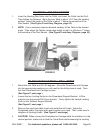
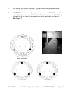
Place the pencil back in the Miter Gauge and align the pencil point and the high
spot together at the infeed end of the Table. Rotate the Saw Blade, and bring the
Miter Gauge and the high spot together at the outfeed of the Table.
The Extension Table is aligned if the pencil tip touches the Saw Blade just the
same touch and place. Make sure all four Hex Head Capscrews attaching the
Table are tight.
The Extension Table is not aligned if the pencil tip pushes the Saw Blade or there
is a gap between the pencil tip and Blade. If the Table is not aligned, loosen all
four Capscrews attaching the Table. Once alignment is achieved, tighten all four
Capscrews.
The Extension Table will now be aligned each time you mount it in the right-hand
end of the machine. NOTE: The Table may be used on the left-hand end of the
machine but will not be aligned with the Saw Blade. Mounting the Extension
Table on the left-hand side of the machine is for extra support only.
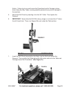
TO SET THE CARRIAGE BUMPER BOLT
With the Saw Blade mounted and the Quill fully retracted, bring the Powerhead
and Carriage together until they touch.
Install the saw Table on the Carriage.
Lower the Table, and look down through the Saw Blade Insert and move the
Carriage left or right as needed to center the Blade in the Saw Insert Slot.
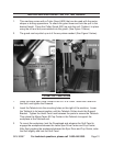
Once the Table is centered over the Saw Blade, lock the Powerhead and
Carriage onto the Way Tubes.
Adjust the Carriage Bumper Bolt on the Carriage so that it just touches the side
of the Powerhead. Then tighten the Locking Nut against the Carriage Casing.
Now each time the Table Saw is set up, the Saw Blade will be centered in the
saw Table Insert Slot.
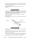
TO ALIGN THE SAW TABLE 90 DEGREES TO THE POWERHEAD
Move the Powerhead about 10” from the Carriage.
Install the saw Table and Drill Chuck/Drill Bit in the Horizontal Boring Tool.
Loosen the Table Trunnion Locks. Then tilt the Table 90 degrees and tighten the
Locks.
Place a T-Square against the Drill Bit and Table surface.
4.
5.
6.
7.
1.
2.
3.
4.
5.
6.
1.
2.
3.
4.