


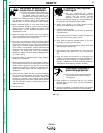
ELECTRICAL OUTPUT
CONNECTIONS
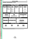
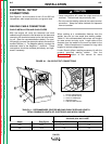
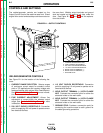
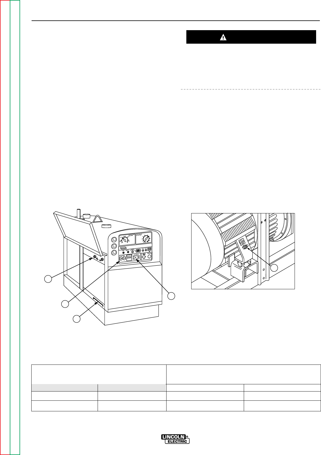
See Figure A.1 for the location of the 115 and 230 volt
receptacles, weld output terminals, and ground stud.
WELDING CABLE CONNECTIONS
CABLE INSTALLATION AND CABLE SIZES
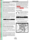
With the engine off, route the electrode and work
cables through the strain relief bracket on the base and
connect to the terminals located on the fuel tank mount-
ing rail. (See size recommendations below.) For posi-
tive polarity, connect the electrode cable to the terminal
marked Positive (+). For Negative polarity, connect the
electrode cable to the Negative (-) terminal. These
connections should be checked periodically and tight-
ened if necessary.
• Loose connections will cause the output terminals to
overheat. The terminals may eventually melt.
• Do not cross the welding cables at the output terminal
connection. Keep the cables isolated and separate
from one another.
When welding at a considerable distance from the
welder, be sure you use ample size welding cables.
Table A.1 lists recommended cable sizes and lengths
for rated current and duty cycle. Length refers to the
distance from the welder to the work and back to the
welder. Cable diameters are increased for long cable
lengths to reduce voltage drops.
Lincoln Electric offers a welding accessory kit with the
properly specified welding cables. See the
Accessories
section of this manual for more
information.
INSTALLATION
A-6 A-6
SA-250
Return to Section TOC Return to Section TOC Return to Section TOC Return to Section TOC
Return to Master TOC Return to Master TOC Return to Master TOC Return to Master TOC
CAUTION
3
1
5
2
4
FIGURE A.1 - SA-250 OUTPUT CONNECTIONS
1. 230 VAC RECEPTACLE
2. 115 VAC RECEPTACLE
3. OUTPUT TERMINALS
4. GROUND STUD
5. CABLE STRAIN RELIEF
TABLE A.1 - RECOMMENDED COPPER WELDING CABLE SIZE AND LENGTH
TOTAL COMBINED LENGTH OF ELECTRODE AND WORK CABLES
Cable sizes for combined length of
electrode plus work cable
Amps Duty Cycle Up to 200 ft. 200 to 250 ft.
250 60% 1 1/0
350 25% 2/0 3/0