


Return to Section TOC Return to Section TOC Return to Section TOC Return to Section TOC
Return to Master TOC Return to Master TOC Return to Master TOC Return to Master TOC
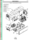
ENGINE, GENERATOR ARMATURE
AND FRAME, ALTERNATOR
STATOR AND ROTOR
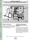
EXCITATION (FLASHING)
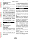
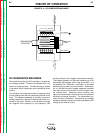
When the engine is started and running, the residual
magnetism voltage is applied to the alternator rotor via
a brush and slip ring configuration. This excitation
(“flashing”) voltage magnetizes the rotor lamination.
The alternator rotor is connected to the armature shaft,
which is mechanically coupled to the engine. This
rotating magnet (rotor) induces a voltage in the station-
ary windings of the alternator stator.
AUXILIARY AND FIELD FEEDBACK COILS
There are two isolated windings incorporated in the sta-
tor lamination assembly. One of these windings is
tapped and provides 115VAC and 230VAC of auxiliary
power to the appropriate receptacles. The other
115VAC isolated winding is rectified to a DC voltage
and is used to supply field feedback voltage to the rotor.
It also, through the generator field rheostat control, sup-
plies voltage to the field shunt windings in the main
generator frame.
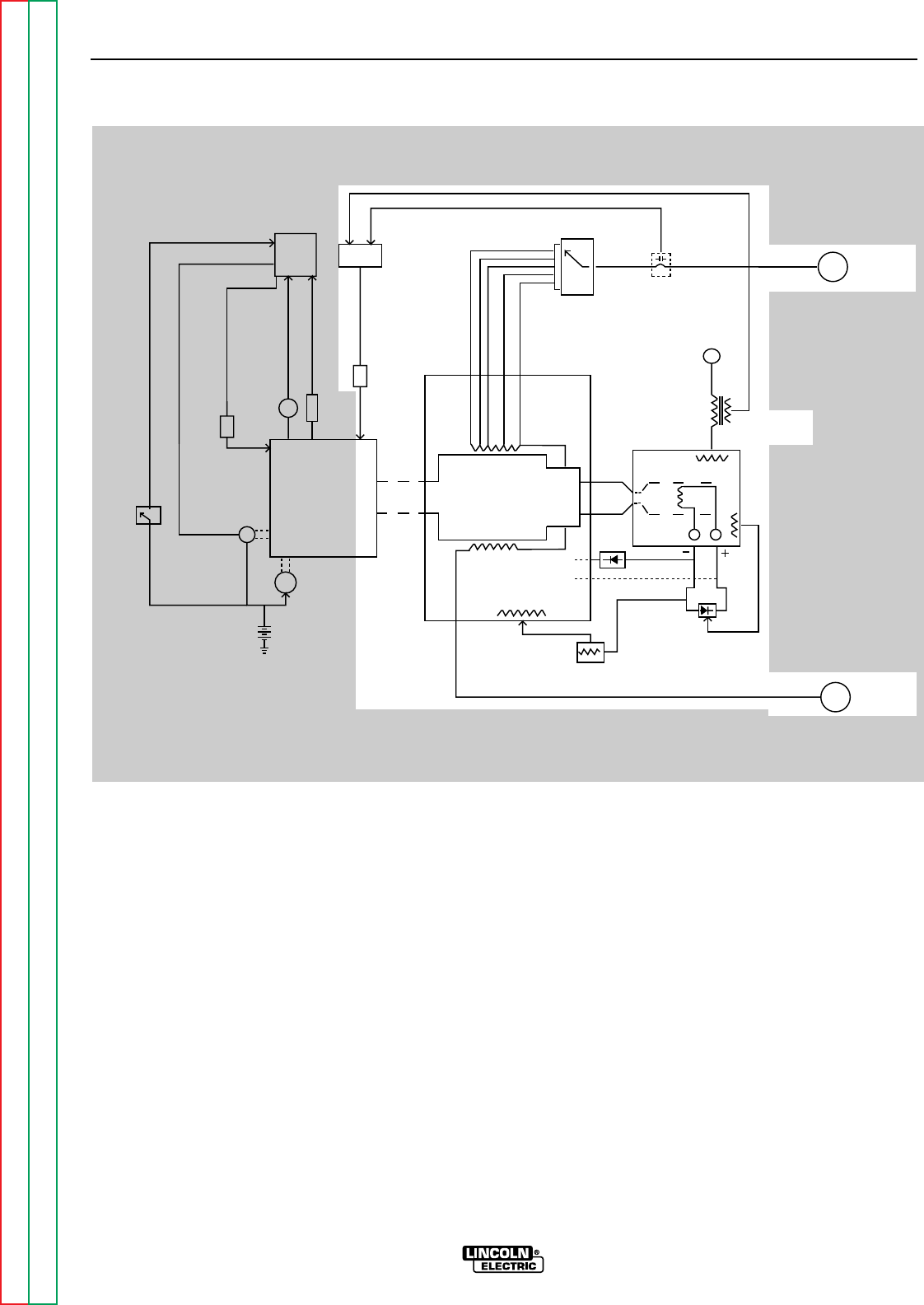
THEORY OF OPERATION
E-3 E-3
SA-250
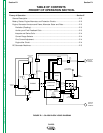
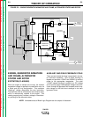
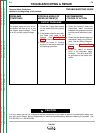
NOTE: Unshaded areas of Block Logic Diagram are the subject of discussion.
FIGURE E.3 – ENGINE GENERATOR ARMATURE AND FRAME, ALTERNATOR STATOR AND ROTOR
NEGATIVE
OUTPUT
TERMINAL
POSITIVE
OUTPUT
TERMINAL
115 & 230VAC
RECEPTACLES
CURRENT
TRANSFORMER
FIELD
RECTIFIER
FLASHING
RESIDUAL
MAGNETISM
ALTERNATOR STATOR
ROTOR
SLIP
RINGS
ARMATURE
SHAFT
GENERATOR
ARMATURE
BRUSHES
&
COMMUTATOR
GENERATOR
FRAME
SERIES
COILS
INTERPOLE
COILS
SHUNT
WINDINGS
GENERATOR
FIELD CONTROL
FIELD
MECHANICAL
COUPLING
REED
RELAY
CR2
SELECTOR
SWITCH
IDLER
BOARD
IDLER
SOLENOID
OIL
PRESSURE
TEMPERATURE
FUEL
ENGINE
ALTERNATOR
STARTER
MOTOR
BATTERY
ENGINE
PROTECTION
RELAY
IGNITION
SWITCH
INJECTION
PUMP
GAUGE
SWITCH