


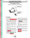
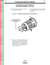
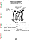
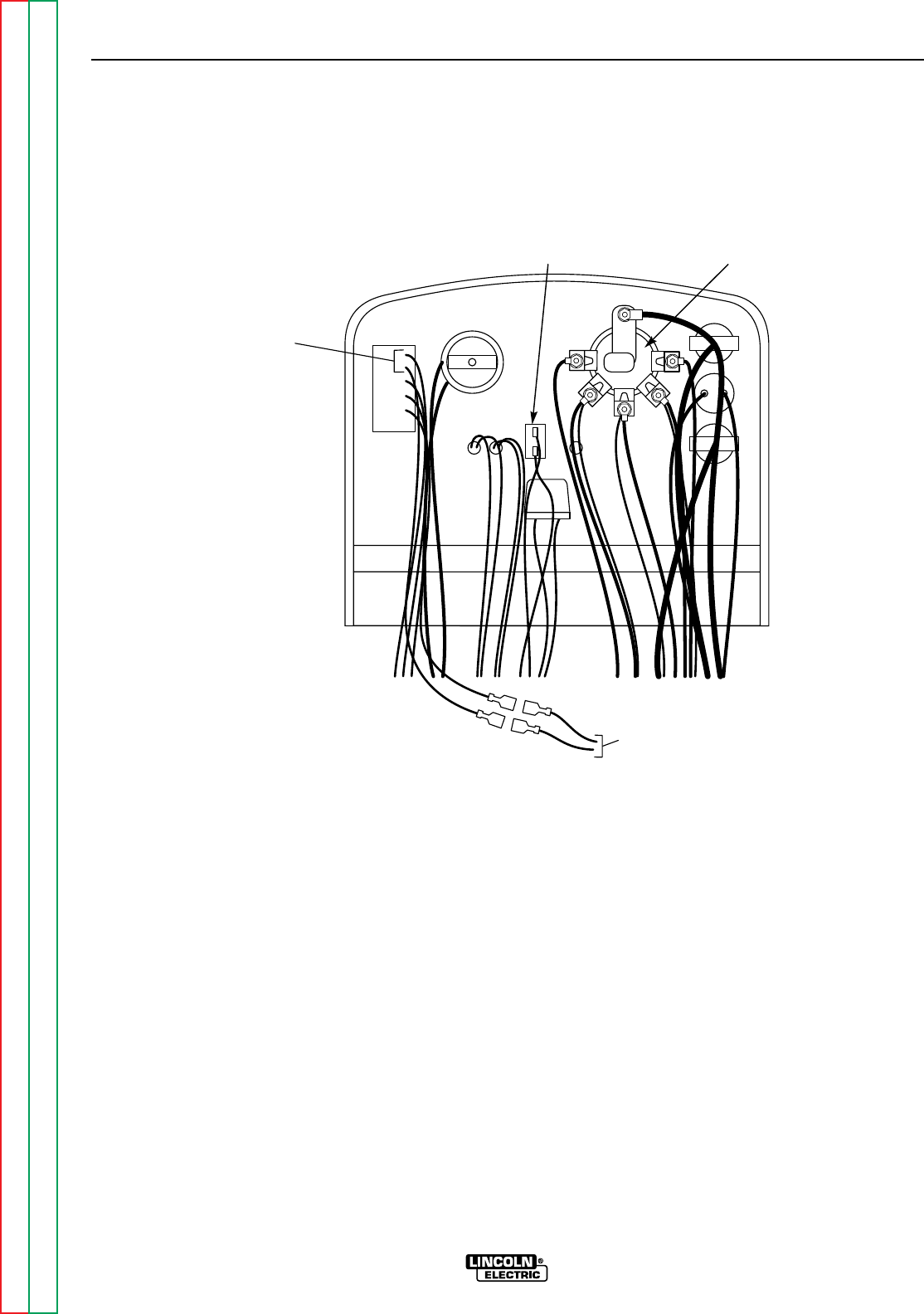
See Figure F.20 for steps 11 - 16.
11. Cut all necessary cable ties.
12. Disconnect the blue and the brown wires at the in-
line connectors. See Figure F.20 and the Wiring
Diagram.
13. Label the cables that are connected to the selector
switch. Otherwise, you will need to see the Wiring
Diagram during reassembly.
NOTE: Some terminals have more than one cable
connected. Tape any pairs together before removing
them.
14. With the 1/2" wrench, remove the cables connect-
ed to the selector switch.
15. Disconnect the current transformer black lead from
circuit breaker CB2.
16. Remove the two blue current transformer leads
from the idler PC board. Note lead location.
TROUBLESHOOTING & REPAIR
F-43 F-43
SA-250
Return to Section TOC Return to Section TOC Return to Section TOC Return to Section TOC
Return to Master TOC Return to Master TOC Return to Master TOC Return to Master TOC
GENERATOR FRAME REMOVAL
AND REPLACEMENT (continued)
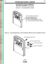
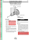
FIGURE F.20 – WIRE AND SELECTOR SWITCH CONNECTIONS
IN-LINE CONNECTOR
BLUE/BROWN LEADS
SELECTOR
SWITCH
CIRCUIT BREAKER CB2
WITH BLACK CURRENT
TRANSFORMER LEAD
IDLER
PC BOARD
BLUE CURRENT
TRANSFORMER
LEADS