


Return to Section TOC Return to Section TOC Return to Section TOC Return to Section TOC
Return to Master TOC Return to Master TOC Return to Master TOC Return to Master TOC
TROUBLESHOOTING & REPAIR
F-16 F-16
SA-250
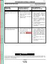
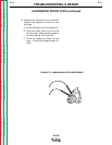
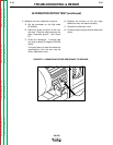
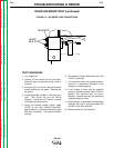
FIGURE F.3 – MEASURING ROTOR RESISTANCE TO GROUND
9. Measure the rotor resistance to ground.
A. Set the ohmmeter on the high scale
(X100,000).
B. Place one probe on either of the rotor
slip rings. Place the other probe on any
good, unpainted ground. See Figure
F.3.
C. Check the resistance. It should read
very high, at least 0.5 megohm (500,000
ohms).
If the test does not meet the resistance
specifications, then the rotor may be
faulty. Replace the rotor.
10. Replace the brushes on the slip rings.
Make sure they are seated correctly.
11. Reinstall the alternator cover.
12. Close and latch the right and left side cover
doors.
ALTERNATOR ROTOR TEST (continued)