


Return to Section TOC Return to Section TOC Return to Section TOC Return to Section TOC
Return to Master TOC Return to Master TOC Return to Master TOC Return to Master TOC
THEORY OF OPERATION
E-5 E-5
SA-250
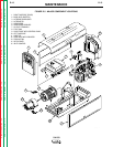
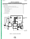
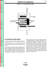
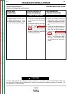
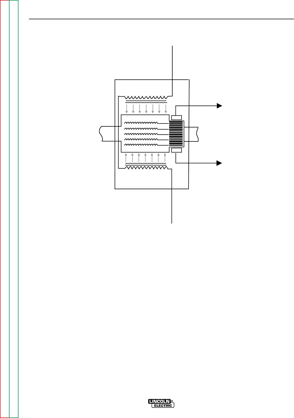
FIGURE E.4 – DC GENERATOR MACHINES
ARMATURE
SHAFT
GENERATOR
ARMATURE
SHUNT
WINDINGS
FIELD
MECHANICAL
COUPLING
SHUNT
WINDINGS
FIELD
B
RUSH
B
RUSH
MAGNETIC FIELD
MAGNETIC FIELD
DC CURRENT
DC CURRENT
F
I
E
L
D
C
U
R
R
E
N
T
F
I
E
L
D
C
U
R
R
E
N
T
DC GENERATOR MACHINES
The armature winding of a DC generator is located on
the rotating member. Current is conducted from it by
means of carbon brushes. The field winding is located
in the stator, which is stationary, and is excited by direct
current.
The armature coil sides are placed at opposite points
on the rotating shaft with the conductors parallel to the
shaft. The armature assembly is normally turned at a
constant speed by a source of mechanical power con-
nected to the shaft. Rotation of the armature through
the magnetic field produced by the stationary field
winding induces a coil voltage in the armature winding.
The voltage induced in an individual armature coil is an
alternating (AC) voltage, which must be rectified. In a
conventional DC Generator, rectification is provided
mechanically by means of a commutator. A commuta-
tor is a cylinder formed of copper segments insulated
from each other and mounted on, but insulated from,
the rotating shaft. Stationary carbon brushes held
against the commutator surface connect the armature
windings to external terminals. The commutator pro-
vides full-wave rectification, transforming the voltage
waveform between brushes and making available a DC
voltage to the external circuit.