


Return to Section TOC Return to Section TOC Return to Section TOC Return to Section TOC
Return to Master TOC Return to Master TOC Return to Master TOC Return to Master TOC
TROUBLESHOOTING & REPAIR
F-21 F-21
SA-250
IDLER SOLENOID TEST (continued)
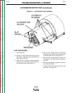
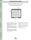
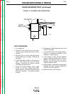
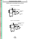
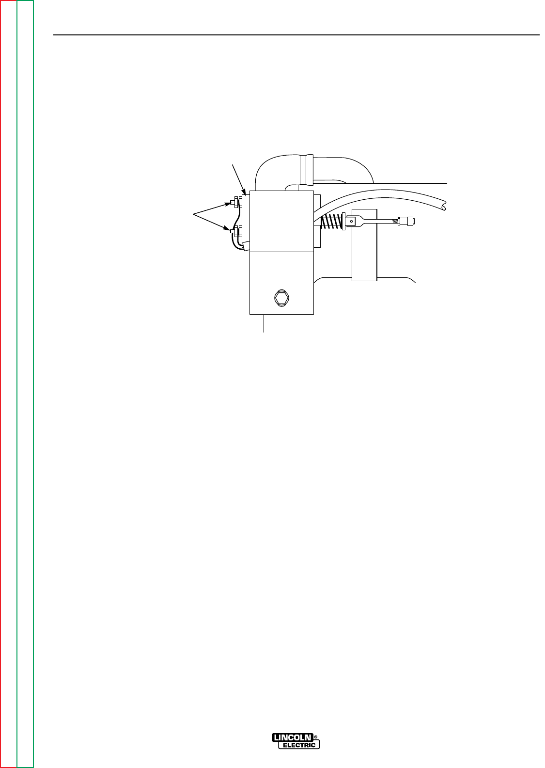
FIGURE F.6 - SOLENOID LEAD CONNECTIONS
LEADS
56 & 57
SOLENOID
TEST PROCEDURE
1. Turn engine off.
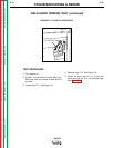
2. Unlatch, lift and secure the left side door.
Note that there are latches at both ends of
the door.
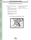
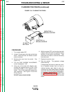
3. Using the 5/16" nut driver, remove the three
screws holding the fan guard. Remove the
fan guard.
4. Locate leads #56 and #57 on the idler sole-
noid. See Figure F.6 and the Wiring
Diagram. Using the 5/16" wrench, remove
the leads from the solenoid.
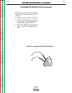
5. Using the external voltage supply, apply
12VDC to the idler solenoid terminals.
Attach positive (+) to the terminal where lead
#56 was connected. The solenoid should
activate.
6. The solenoid should deactivate when the
12VDC is removed.
7. If the solenoid does not operate properly,
check for a mechanical restriction in the
linkage or a missing spring.
8. If the linkage is intact and the solenoid
does not operate correctly when 12VDC is
applied, the solenoid may be faulty.
Replace. Normal solenoid coil resistance
is approximately 9 ohms.
9. When the test is complete and the problem
repaired, be sure to reconnect leads #56
and #57 to the idler solenoid.
10. Close and latch the left side door.