


WELDING OPERATION
TO USE THE SA-250 FOR DC CONSTANT
CURRENT STICK OR TIG WELDING:
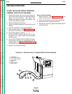
1. Remove the flange nuts from the weld output ter-
minals and place the work and electrode welding
cables over the terminals. See Figure B.4.
Replace and tighten the flange nuts securely. Be
sure the connections are tight.
2. Select the appropriate electrode.
3. Attach the work clamp securely to the work you are
welding.
4. Insert the electrode into the electrode holder.
5. Start the diesel engine. See
Engine Operation
in
this section of the manual.
6. Set the Idler Switch to “AUTO.”
7. Set the CURRENT RANGE SELECTOR to a set-
ting equal to or slightly higher than the desired
welding current.
8. Set the FINE CURRENT ADJUSTMENT to the set-
ting that gives the best arc characteristics for the
range selected. See
Control of Welding Current
in this section of the manual.
9. Strike an arc and begin welding.
After you finish welding:
1. Stop the engine. See
Engine Operation
in this
section of the manual.
2. Allow the electrode and work to cool completely.
3. Remove the work clamp from the work.
4. Remove any remaining piece of electrode from the
electrode holder.
OPERATION
B-10 B-10
SA-250
Return to Section TOC Return to Section TOC Return to Section TOC Return to Section TOC
Return to Master TOC Return to Master TOC Return to Master TOC Return to Master TOC
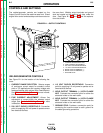
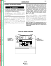
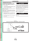
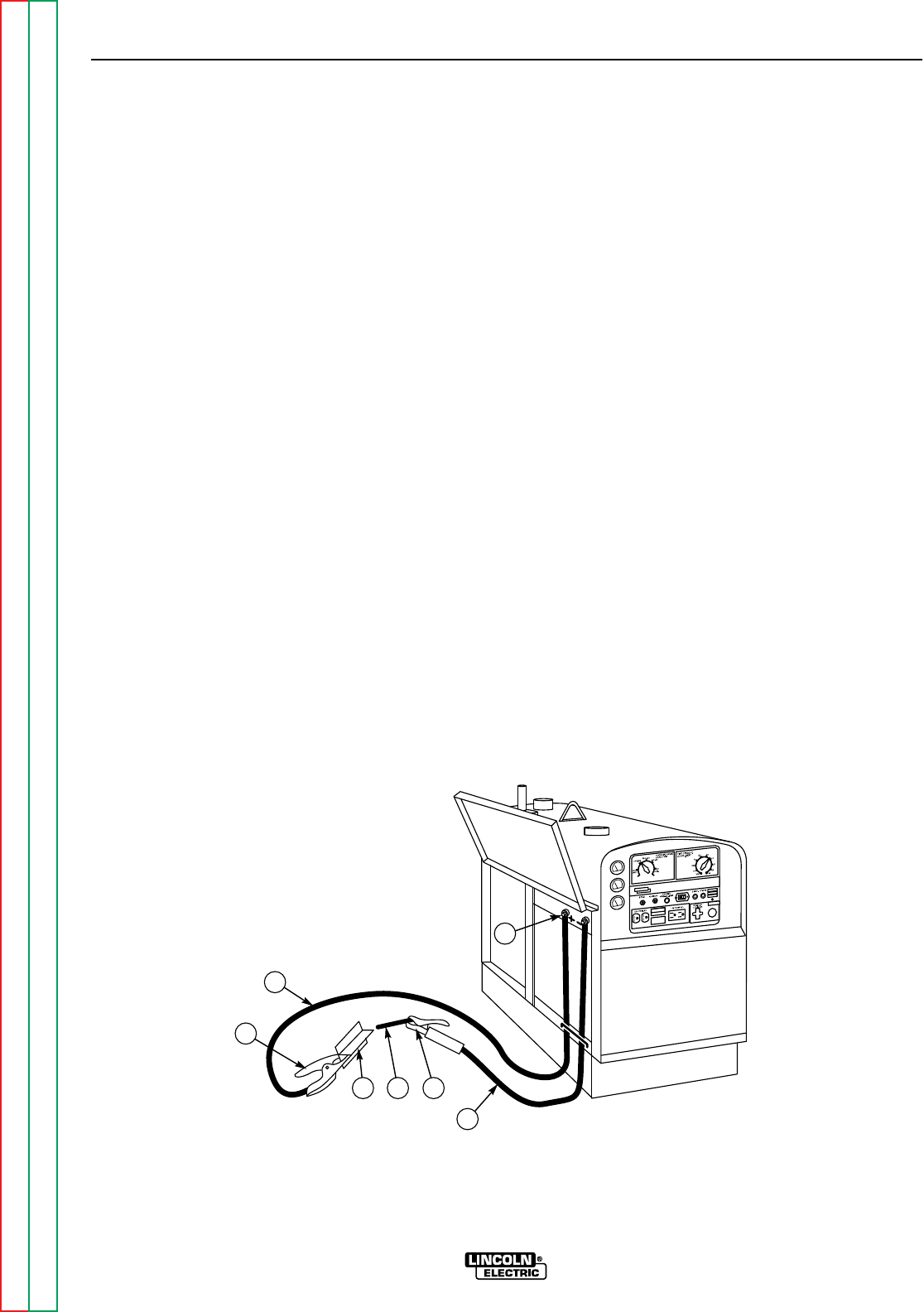
FIGURE B.4 – WELDING CIRCUIT CONNECTIONS FOR STICK WELDING
2
1
7
6
54
3
1. FLANGE NUT
2. ELECTRODE CABLE
3. ELECTRODE HOLDER
4. ELECTRODE
5. WORK
6. WORK CLAMP
7. WORK CABLE