


Return to Section TOC Return to Section TOC Return to Section TOC Return to Section TOC
Return to Master TOC Return to Master TOC Return to Master TOC Return to Master TOC
TROUBLESHOOTING & REPAIR
F-24 F-24
SA-250
ENGINE THROTTLE ADJUSTMENT TEST (continued)
6. If either of the readings is incorrect, adjust
the throttle as follows:
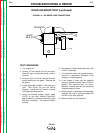
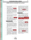
Adjust HIGH IDLE: Use the 8mm wrench to
loosen the locking nut. See
Figure F.8
for
location of the adjusting screw and locking
nut. Avoid breaking the seal. There should
be enough play to allow adjustment without
disturbing the seal. Turn the threaded screw
counter-clockwise to increase the HIGH
IDLE speed. Adjust the speed until the tach
reads between 1780 and 1810 RPM.
Retighten the locking nut.
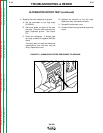
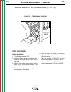
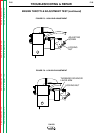
Adjust LOW IDLE: First make sure there is
no load on the machine. Set the IDLE
switch to AUTO and wait for the engine to
change to low idle speed.
Use the 7/16" wrench to loosen the solenoid
lever arm locking nut. See
Figure F.9.
Adjust the threaded solenoid lever arm
shaft, to change the amount of throw in the
lever arm, until the tach reads between 1350
and 1400 RPM. Retighten the locking nut.
Frequency Counter Method
1. Plug the frequency counter into one of the
115 VAC auxiliary receptacles.
2. Start the engine and check the frequency
counter. At HIGH IDLE (1800 RPM), the
counter should read 60 Hz. At LOW IDLE
(1400 RPM), the counter should read 47 Hz.
Note that these are median measurements;
hertz readings may vary slightly above or
below.
3. If either of the readings is incorrect, adjust
the throttle as follows:
Adjust HIGH IDLE: Use the 8mm wrench to
loosen the locking nut. See
Figure F.8
for
location of the adjusting screw and locking
nut. Avoid breaking the seal. There should
be enough play to allow adjustment without
disturbing the seal. Turn the threaded screw
counter-clockwise to increase the HIGH
IDLE speed. Adjust the speed until the fre-
quency reads 60 Hz. Retighten the locking
nut.
Adjust LOW IDLE: First make sure there is
no load on the machine. Set the IDLE
switch to AUTO and wait for the engine to
change to low idle speed. Use the 7/16"
wrench to loosen the solenoid lever arm
locking nut. See
Figure F.9.
Adjust the
threaded solenoid lever arm shaft, to
change the amount of throw in the lever
arm, until the frequency reads 47 Hz.
Retighten the locking nut.
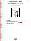
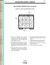
Oscilloscope Method
1. Connect the oscilloscope to the 115 VAC
receptacle, according to the manufacturer’s
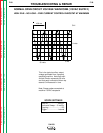
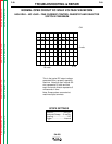
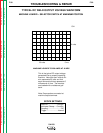
instructions. At HIGH IDLE (1800 RPM), the
waveform should exhibit a period of 16.6
milliseconds. At LOW IDLE (1400 RPM),
the waveform should exhibit a period of 21.4
milliseconds. Refer to the
NORMAL OPEN
CIRCUIT VOLTAGE WAVEFORM (115
VAC SUPPLY) HIGH IDLE - NO LOAD
in
this section of the manual.
2. If either of these periods is incorrect, adjust
the throttle as follows:
Adjust HIGH IDLE: Use the 8mm wrench to
loosen the locking nut. See
Figure F.8
for
location of the adjusting screw and locking
nut. Avoid breaking the seal. There should
be enough play to allow adjustment without
disturbing the seal. Turn the threaded screw
counter-clockwise to increase the HIGH
IDLE speed. Adjust the speed until the peri-
od is 16.6 milliseconds. Retighten the lock-
ing nut.
Adjust LOW IDLE: First make sure there is
no load on the machine. Set the IDLE
switch to AUTO and wait for the engine to
change to low idle speed. Use the 7/16"
wrench to loosen the solenoid lever arm
locking nut. See
Figure F.9.
Adjust the
threaded solenoid lever arm shaft, to
change the amount of throw in the lever
arm, until the period is 21.4 milliseconds.
Retighten the locking nut.