


Return to Section TOC Return to Section TOC Return to Section TOC Return to Section TOC
Return to Master TOC Return to Master TOC Return to Master TOC Return to Master TOC
TROUBLESHOOTING & REPAIR
F-27 F-27
SA-250
FLASHING THE FIELDS (continued)
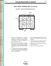
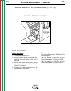
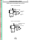
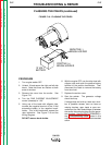
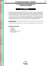
FIGURE F.10 - FLASHING THE FIELDS
NEGATIVE(-)
BRUSH HOLDER
POSITIVE (+)
BRUSH HOLDER
12 VOLT
BATTERY
_
+
PROCEDURE
1. Turn engine welder OFF.
2. Unlatch, lift and secure the right and left side
doors. Note that there are latches at both
ends of the door.
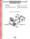
3. Remove the cover from the exciter. See
Figure F.10.
4. Turn the FINE CURRENT ADJUSTMENT
control (rheostat) to “100.”
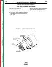
5. Using one of the leads with alligator clips,
connect the negative terminal of the 12-volt
automotive battery to the negative brush-
holder. This is the brushholder nearest the
rotor lamination. See Figure F.10 and the
Wiring Diagram.
DO NOT remove brush holder.
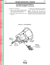
6. With the engine OFF, use the other lead with
alligator clips and touch the positive battery
terminal to the positive brushholder. Then
disconnect the leads to remove the battery
from the circuit.
7. Replace the exciter cover.
8. Start the welder. The generator voltage
should build up.
If voltage does not build up, there are a num-
ber of possible causes, such as loose or
missing brushes, open leads or poor con-
nections at the field diode bridge or between
the exciter alternator brushes and the gener-
ator brushes. See OUTPUT PROBLEMS in
the
Troubleshooting Guide
located in this
section of the manual for recommended
action.