


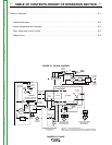
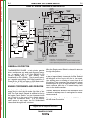
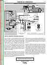
THEORY OF OPERATION
E-2 E-2
RANGER® 3 PHASE
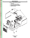
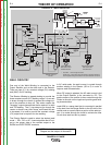
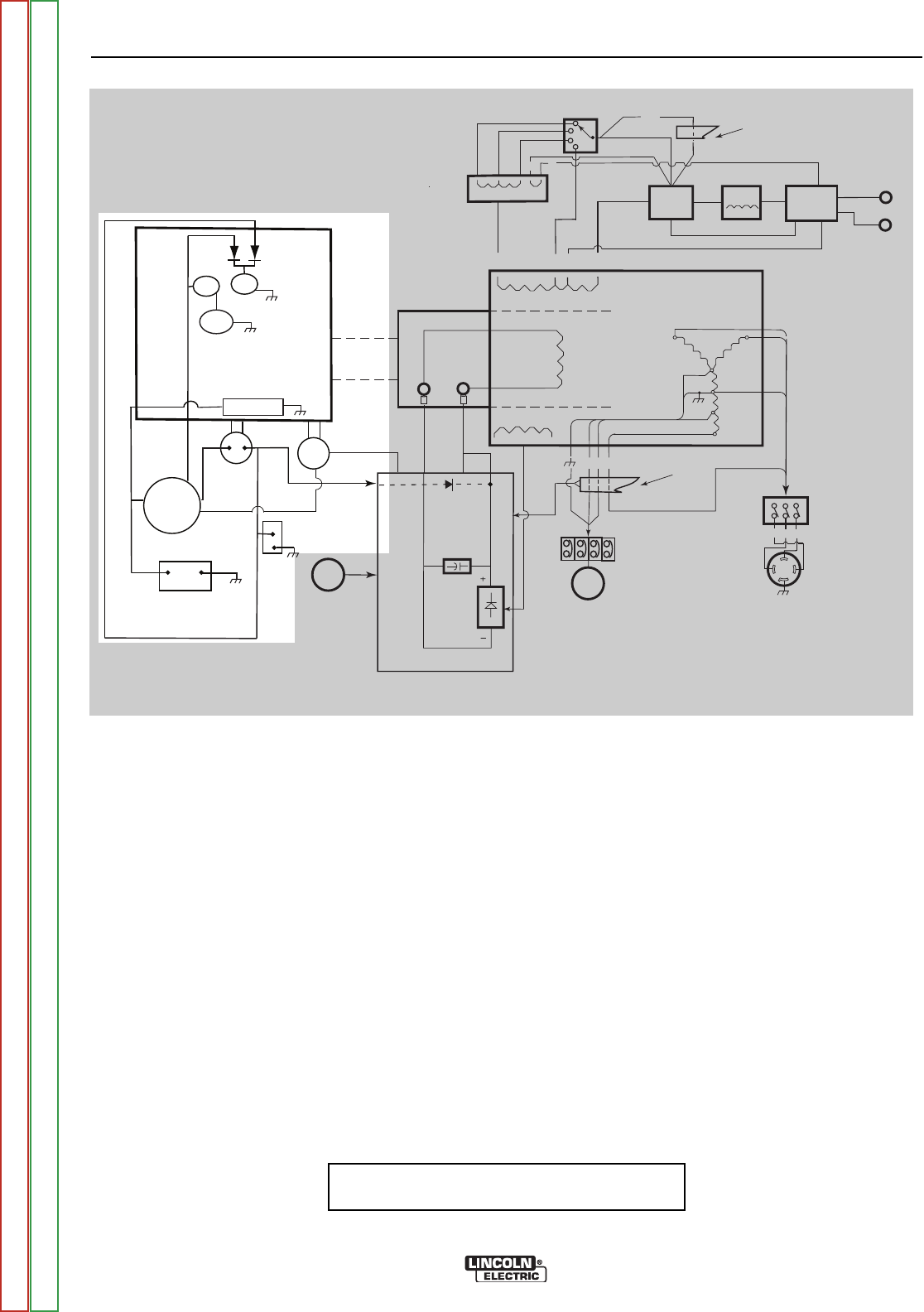
FIGURE E.2 - ENGINE COMPONENTS AND OPERATION
NOTE: Unshaded areas of Block Logic
Diagram are the subject of discussion
GENERAL DESCRIPTION
The RANGER® 3 PHASE is a twin cylinder, gasoline
driven, multiprocess arc welder and AC power genera-
tor. It is capable of AC or DC Stick (SMAW) or TIG
(GTAW) welding and CV Wire welding, either
Innershield® or MIG (GMAW). The AC power genera-
tor is capable of providing 10,500 Watts continuous, 3
Phase 60 Hz. AC 480 volt power or 9500 Watts contin-
uous, Single Phase 60 Hz. AC 120/240 volt power.
ENGINE COMPONENTS AND OPERATION
The Engine Control Switch is used to start and stop the
engine and to select the idle mode (High Idle or Auto
Idle). The Fuel Shutoff Solenoid is activated at first by
the Engine Control Switch. Then, as oil pressure builds
up it is held in by the output of the voltage regulator
through the oil pressure switch. If the oil pressure
switch opens for any reason, the Fuel Solenoid will
release and the engine will shut down.
When the Engine control Switch is released it returns to
the High Idle position.
When the switch is placed in the Auto Idle position, after
a delay of approximately 10 seconds, the Idler Solenoid
will energize and the engine will drop to low speed.
Upon striking an arc or drawing of current from any of
the Auxiliary Power receptcles, the solenoid will release
and the engine will go to the high idle speed. Once the
load is removed, and after a 10 second delay, it will
return to the low idle condition.
The Hour Meter runs whenever the oil pressure switch
is closed to help keep track of running time for mainte-
nance concerns.
Turning the Engine Control Switch to the ‘OFF’ Position
will shut down the machine.
IDLER
SOLENOID
OUTPUT
CONTROL
MECHANICAL
ROTATION
FIELD
CAPACITOR
SLIP
RINGS
RANGE
SWITCH
OUTPUT
BRIDGE
CHOKE
AC
AC
WORK
TERMINAL
PRINTED CIRCUIT
BOARD
TOROIDTOROID**
ENGINE
FLYWHEEL ALTERNATOR/
VOLTAGE REGULATOR
BATTERY
HOUR
METER
OIL
PRESSURE
SWITCH
+
-
STARTER
FUEL
SHUTOFF
SOLENOID
STARTER
SOLENOID
ENGINE
CONTROL
SWITCH*
4
3
2
1
Z Y
3
5
6
X
120 & 230 VOLT
BREAKERS AND
RECEPTACLES
EXCITER
WINDING
AUXILIARY
WINDINGS
WELD WINDINGS
Z X Y
480 VOLT 3 PHASE
BREAKER AND
RECEPTACLE
W2
C1
W1
TOROIDTOROID**
254
3 6 X
*
Lead 254 - 1 turn through the toroid
Leads 3 & 6 - two turns through the toroid in opposite directions.
Lead X passes though the toroid in the same direction as lead 6
STATOR
+
--
ELECTRODE
TERMINAL
POLARITY
SWITCH
ROTOR
FLASHING
DIODE
E
S2
WAC
REACTOR
7 9
Return to Section TOC Return to Section TOC Return to Section TOC Return to Section TOC
Return to Master TOC Return to Master TOC Return to Master TOC Return to Master TOC