


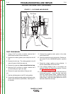
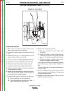
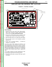
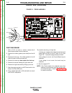
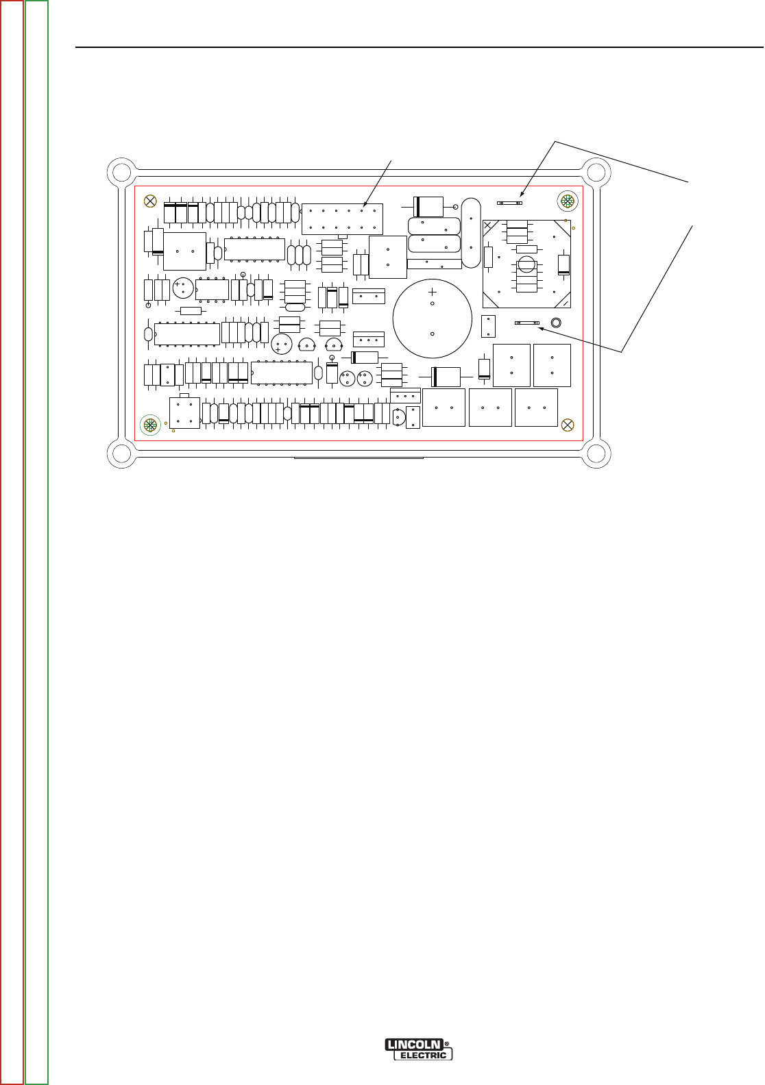
FIGURE F.4 – CONTROL PC BOARD
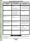
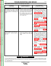
AUXILIARY AND FIELD WINDING TEST (continued)
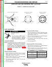
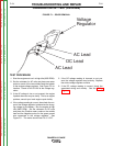
FIELD WINDING
1. Remove the fuel cap and lift bail rubber gasket.
With a 5/16” nut driver or socket, remove the case
top and left side; then reinstall the fuel cap.
2. Connect the volt/ohmmeter probes to leads #7 and
#9 where they connect to the Control P.C. Board.
3. Start the engine and run it at high idle (3700 RPM).
4. Set the output control to the maximum position
(position 10).
5. Check the AC voltage reading. It should be
between 41 and 45 VAC.
If any one or more of the readings are missing or not
within specifications, then check for loose or broken
wires between the test points and the stator windings.
See the Wiring Diagram. Make sure the windings are
NOT grounded internally to the stator iron. If the leads
are intact, then the stator may be faulty. Replace the
stator.
If the voltage readings are within specifications, then
the windings are good and functioning properly.
6. Reinstall the case side, case top, fuel cap, and lift
bail gasket
TROUBLESHOOTING AND REPAIR
F-17 F-17
RANGER® 3 PHASE
B
A
D
C
CONTROL
L12198-1
X4
DZ5
D1
C24
C39
R4
D2
X3
C31
R33
R76
R95
R82
R39
Q3
R47
C12
R72
R67
C37
R88
R45
J2
R48
D3
C30
C32
DZ8
D11
D10
C2
R5
TP2
D21
R73
D9
DZ2
DZ10
R11
Q1
R16
DZ9
R10
Q5
R52
R83
R57
D19
R12
C40
C41
R79
C36
R81
R29
R89
R41
DZ4
R84
R80
Q4
R21
R32
R96
C14
R91R40
C26
R20
R85
R69
C10
C13
R17
R23
C1
R44
D16
X1
R58
R42
R75
R49
D14
C29
R43
DZ7
C38
TP1
D15
R7
R94
DZ1
J1
C23
X5
DZ3
R31
C3
R66
R51
C35
R62
R70
D28
R100
DZ11
R19
B1
C43
R13
C27
R34
D18
R14
C28
R15
R56
R102
R97
R18
C4
C42
R46
R101
R74
R65
B2
R87
D4
R98
Q6
C22
R53
R99
R77
R68
R78
C19
R71
C7
FTP1
FIELD VOLTAGE
(Leads #7 & #9)
16
7 12
Lead #219 (J1, Pin 5)
Return to Section TOC Return to Section TOC Return to Section TOC Return to Section TOC
Return to Master TOC Return to Master TOC Return to Master TOC Return to Master TOC