


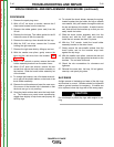


PROCEDURE
Before starting the following procedure, refer to the
topic “PC Board Troubleshooting Procedures” at the
beginning of this section.
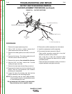
1. Remove the engine spark plug wires.
2. With a 5/16” nut driver or socket, remove the 6
sheet metal screws from the case top.
3. Remove the rubber gasket (cover seal) from the lift
bail.
4. Remove the fuel cap. The rubber gasket for the fill
tube will come off with the case top.
5. Remove the case top, then reinstall the fuel cap.
6. With the 5/16” nut driver, remove the 5 screws
holding the right case side.
7. Remove the right case side by lifting up and out.
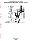
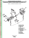
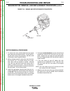
8. Remove the 12-pin and 4 pin molex plugs from
the Printed circuit board.
9. Remove leads 7 and 9 from two 1/4” Q.C. connec-
tors from the board.
10. With a 1/4” phillips head screw driver, remove four
self tapping screws holding the printed circuit
board to the panel.
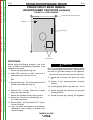
Be sure to follow the recommended static-free meth-
ods for handling printed circuit boards. Failure to do so
can result in permanent damage to the equipment.
11. Replace the old printed circuit board with a new
one.
12. Replace 4 self tapping screws previously
removed.
13. Connect the two Molex plugs and the 7 and 9
leads to P.C. Board.
14. Replace any cable ties that were cut during the
removal procedure.
15. Reinstall the case side, fuel cap, lift bail gasket,
case top, and spark plug wires.
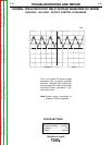
12 Pin Plug
4 Pin Plug
4 Self Tapping Screws (at corners)
1/4" Q.C. Tabs
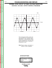
FIGURE F.10 – DOOR REMOVAL
PRINTED CIRCUIT BOARD REMOVAL
AND REPLACEMENT PROCEDURE (continued)
TROUBLESHOOTING AND REPAIR
F-44 F-44
RANGER® 3 PHASE
CAUTION
Return to Section TOC Return to Section TOC Return to Section TOC Return to Section TOC
Return to Master TOC Return to Master TOC Return to Master TOC Return to Master TOC