


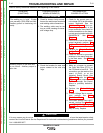
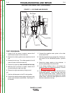
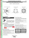
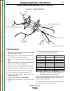
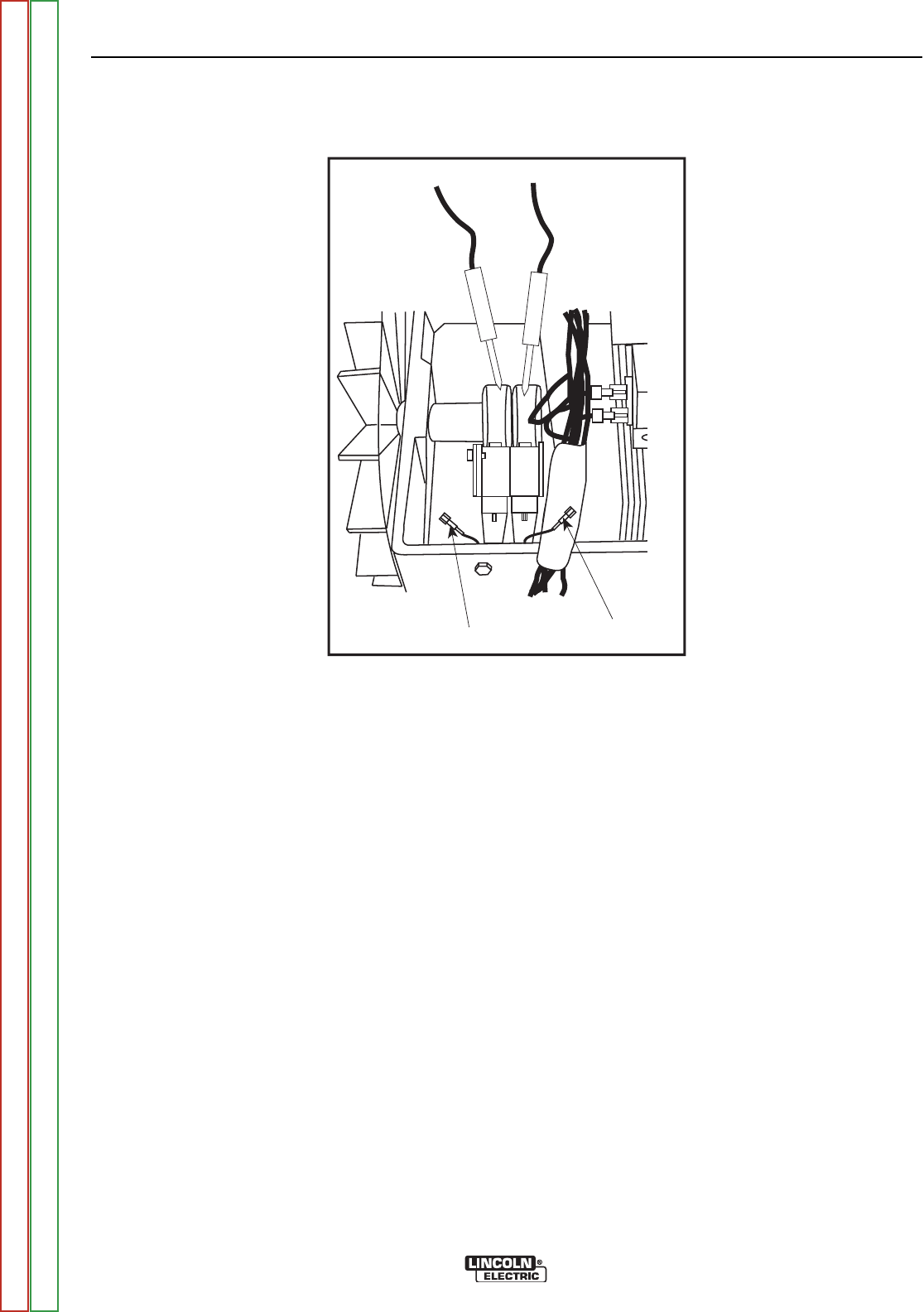
Lead 219
Lead 200A
+
-
FIGURE F.2 – SLIP RINGS
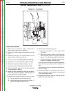
ROTOR RESISTANCE TEST (continued)
TEST PROCEDURE
1. With a 5/16” nut driver or socket, remove the 6
sheet metal screws from the case top.
2. Remove the rubber gasket (cover seal) from the lift
bail.
3. Remove the fuel cap. The rubber gasket for the fill
tube will come off with the case top.
4. Remove the case top, then replace the fuel cap.
5. Remove the 5 screws holding the right case side.
6. Remove the right case side by lifting up and out.
7. Conduct the test with the gasoline engine OFF.
8. Remove the spark plug wires to prevent accidental
engine kickback or starting.
9. Isolate the rotor electrically by removing the gener-
ator brush leads (#219 & #200). Refer to Figure F.2
as you perform the remaining steps.
12. Measure the resistance across the rotor slip rings.
A. Set the ohmmeter on the low scale (X1).
B. Check the resistance across the slip rings. It
should read approximately 5 ohms.
13. Measure the resistance to ground.
A. Set the ohmmeter on the high scale
(X100,000).
B. Place one probe on either of the slip rings.
Place the other probe on any good, unpainted
ground. The machine ground stud works well.
C. Check the resistance. It should read very high,
at least 0.5 megohm (500,000 ohms).
If the test does not meet the resistance specifica-
tions, then the rotor may be faulty. Replace the
rotor.
If the test does meet the resistance specifications,
the rotor is okay.
14. Connect lead 200A to the positive brush, which is
the one nearest the rotor lamination. Connect lead
219 to the negative brush.
15. Reinstall the case side, case top, fuel cap, lift bail
gasket and spark plug wires.
TROUBLESHOOTING AND REPAIR
F-14 F-14
RANGER® 3 PHASE
Return to Section TOC Return to Section TOC Return to Section TOC Return to Section TOC
Return to Master TOC Return to Master TOC Return to Master TOC Return to Master TOC