


TROUBLESHOOTING AND REPAIR
F-31 F-31
RANGER® 3 PHASE
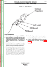
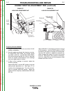
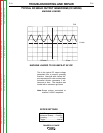
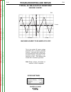
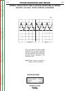
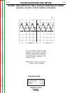
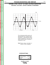
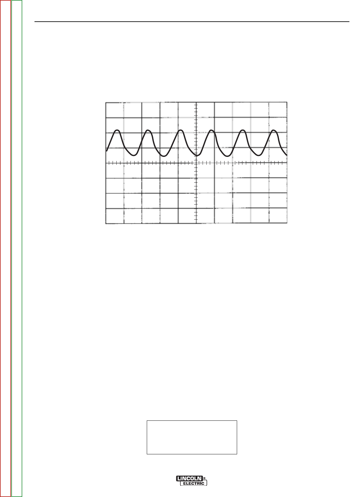
This is the typical DC output voltage
generated from a properly operating
machine. Note that each vertical divi-
sion represents 20 volts and that each
horizontal division represents 5 mil-
liseconds in time. The machine was
loaded with a resistance grid bank.
Note: Scope probes connected at
machine 115VAC receptacle.
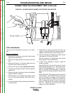
SCOPE SETTINGS
Volts/Div.....................20V/Div.
Horizontal Sweep.....5 ms/Div.
Coupling.............................DC
Trigger.........................Internal
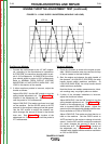
TYPICAL DC WELD OUTPUT WAVEFORM (CC MODE)
MACHINE LOADED
MACHINE LOADED TO 200 AMPS AT 26 VDC
CH1
0 volts
5 ms
20 volts
Return to Section TOC Return to Section TOC Return to Section TOC Return to Section TOC
Return to Master TOC Return to Master TOC Return to Master TOC Return to Master TOC