


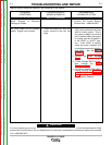
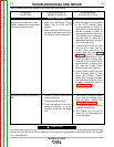
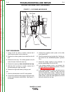
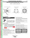


Slip Rings
Brushes
Lead 219
+
-
Lead 200A
FIGURE F.1 – SLIP RINGS AND BRUSHES
ROTOR VOLTAGE TEST (continued)
TEST PROCEDURE
1. Using a 5/16” nut driver or socket, remove the 6
sheet metal screws from the case top.
2. Remove the rubber gasket (cover seal) from the lift
bail.
3. Remove the fuel cap. The rubber gasket for the fill
tube will come off with the case top.
4. Remove the case top, then reinstall the fuel cap.
5. With the 5/16” nut driver or socket, remove the 5
screws holding the right case side.
6. Remove the right case side by lifting up and
out.
7. Set the volt/ohmmeter to the DC volts position.
8. Connect the positive meter probe to the brush near-
est the rotor lamination (lead 200A). See Figure F.1
for location.
9. Connect the negative meter probe to the other
brush (lead 219).
10. Start the engine and run it at high idle. Set the out-
put control to the MAXIMUM position (position
10).]
11. Check the voltage reading on the voltmeter. It
should read between 32 and 45 VDC.
12. If the voltage reading is low or not present, the
generator field is not functioning properly. Perform
the Rotor Resis tance Test.
13. If the voltage reading is normal, the field circuit is
functioning properly. Install the right case side
with the 5 sheet metal screws. Remove the fuel
cap; install the case top and tighten the 6 sheet
metal screws. Install the rubber gasket over the lift
bail and reinstall the fuel cap.
TROUBLESHOOTING AND REPAIR
F-12 F-12
RANGER® 3 PHASE
Return to Section TOC Return to Section TOC Return to Section TOC Return to Section TOC
Return to Master TOC Return to Master TOC Return to Master TOC Return to Master TOC