


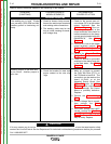
OUTPUT PROBLEMS
Observe Safety Guidelines detailed in the beginning of this manual.
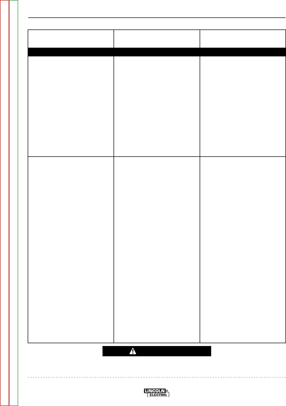
PROBLEMS
(SYMPTOMS)
POSSIBLE AREAS OF
MISADJUSTMENT(S)
RECOMMENDED
COURSE OF ACTION
If for any reason you do not understand the test procedures or are unable to perform the tests/repairs safely,
contact the Lincoln Electric Service Department for technical troubleshooting assistance before you proceed.
Call 1-888-935-3877.
CAUTION
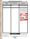
No AC welding output. DC welding
output and auxiliary power is nor-
mal.
1. Make sure the Polarity Switch is
in the proper position and is
“seated” correctly.
2. Make sure the electrode is cor-
rect for the process being used.
3. Make sure the welding cables are
not coiled or too long.
1. Check the operation of the
Polarity Switch (S2). Also check
the associated wires for loose or
faulty connections. See Wiring
Diagram.
2. Check for continuity from lead
“S2” to lead “E” located in the
main stator. See
Wiring Dia -
gram
.
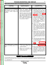
No constant voltage (CV) welding
output. Constant current (CC) and
the auxiliary power are operating
normally.
1. Make sure the Range Switch
(S1) is in the proper position (CV)
and “seated” correctly.
2. Make sure the wire feeder is con-
nected correctly.
1. Check the operation of the
Range Switch (S1) and check
the associated wires for loose or
faulty connections. See Wiring
Diagram.
2. Check for continuity from lead
C1 to lead W1 located in the
main stator. See Wiring Dia -
gram.
TROUBLESHOOTING AND REPAIR
F-6 F-6
RANGER® 3 PHASE
Return to Section TOC Return to Section TOC Return to Section TOC Return to Section TOC
Return to Master TOC Return to Master TOC Return to Master TOC Return to Master TOC