


TROUBLESHOOTING AND REPAIR
F-34 F-34
RANGER® 3 PHASE
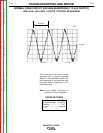
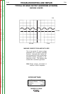
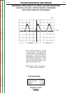
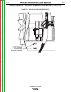
This is NOT the typical DC (+) output
voltage waveform. One output diode
is not functioning. Note the “gap” in
the waveform. One output diode was
disconnected to simulate an open or
nonfunctioning output diode. Each
vertical division represents 50 volts
and each horizontal division repre-
sents 5 milliseconds in time.
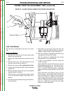
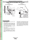
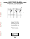
Note: Scope probes connected at
machine 115VAC receptacle.
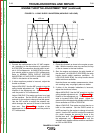
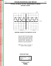
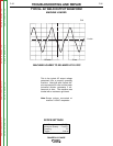
SCOPE SETTINGS
Volts/Div.....................50V/Div.
Horizontal Sweep.....5 ms/Div.
Coupling.............................DC
Trigger.........................Internal
ABNORMAL OPEN CIRCUIT DC WELD VOLTAGE WAVEFORM
HIGH IDLE - NO LOAD - OUTPUT CONTROL AT MAXIMUM
ONE OUTPUT DIODE NOT FUNCTIONING
CH1
0 volts
5 ms
50 volts
Return to Section TOC Return to Section TOC Return to Section TOC Return to Section TOC
Return to Master TOC Return to Master TOC Return to Master TOC Return to Master TOC