


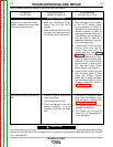
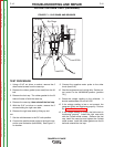
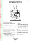
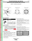
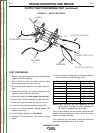
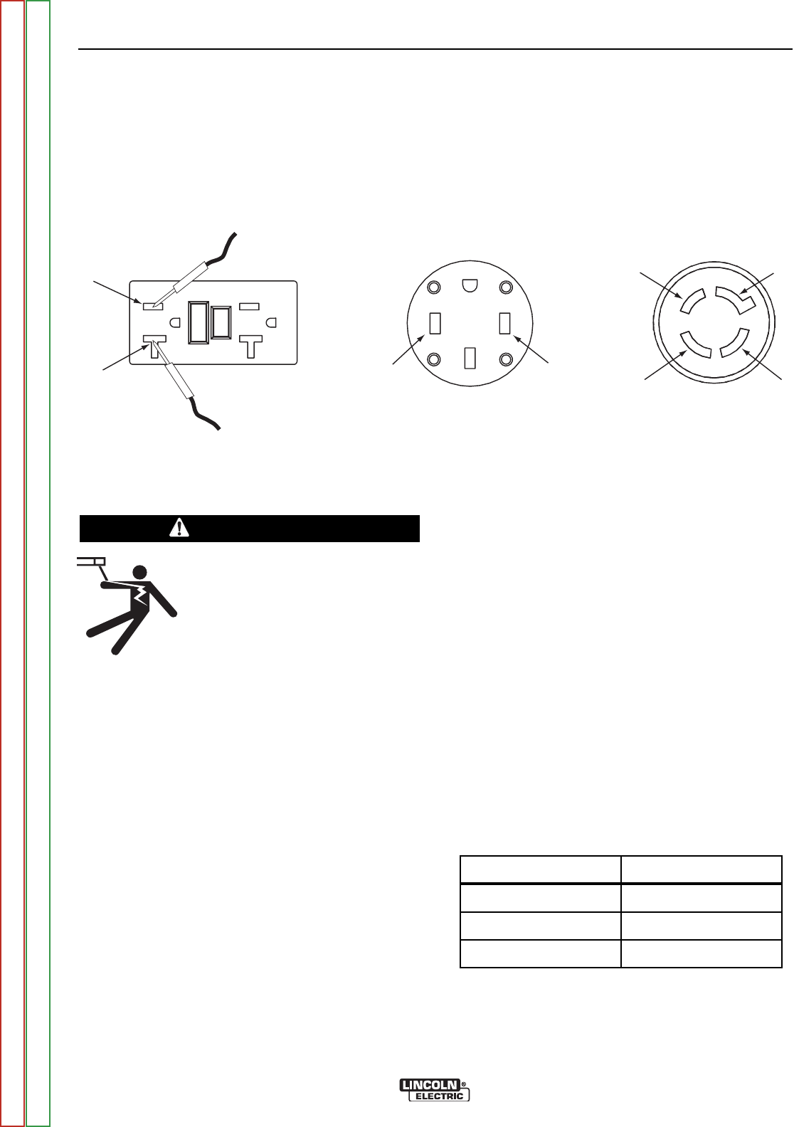
120 VAC GFCI RECEPTACLE
120/240 VAC 1 PHASE
RECEPTACLE
480 VAC 3 PHASE
RECEPTACLE
TEST
RESET
Lead #3
Lead #5
Lead #6
Lead #3
Z
YX
GND
FIGURE F.3 – RECEPTACLES AND LEADS
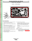
AUXILIARY AND FIELD WINDING TEST (continued)
TEST PROCEDURE
AUXILIARY WINDINGS
NOTE: The following tests can be made by carefully
inserting the meter probes into the receptacles
as indicated. If the probes do not make or
maintain contact, the measurements can be
made on the back of the receptacles or on the
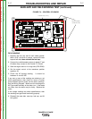
appropriate Circuit Breaker. See the Wiring
Diagram.
To test the 120 VAC winding:
1. With the Voltmeter set to read AC Volts (use proper
scale), place the probes in one of the 120VAC
receptacles as shown in Figure F.3.
2. With the Output Control set at ‘10’, Start the engine
and let it run in the HIGH idle mode.
3. The voltmeter should read 120 to 132 volts from
lead #3 to lead #5.
4. Turn the engine OFF.
To test the 240 VAC winding:
1. With the Voltmeter set to read AC Volts (use proper
scale), place the probes in the 240VAC receptacle
where shown in Figure F.3.
2. With the Output Control set at ‘10’, Start the engine
and let it run in the HIGH idle mode.
3. The voltmeter should read 240 to 264 volts from
lead #3 to lead #6.
4. Turn the engine OFF.
To test the 480 VAC 3 Phase winding:
1. With the Output Control set at ‘10’, Start the engine
and let it run in the HIGH idle mode.
2. Set the voltmeter to the proper scale and check the
voltage readings per the following table:
3. Turn the engine OFF
TROUBLESHOOTING AND REPAIR
F-16 F-16
RANGER® 3 PHASE
WARNING
ELECTRIC SHOCK
can kill.
•
Turn the machine OFF before
working on equipment or making
the meter connections. Do not
touch electrically hot parts.
PROBES READING
X to Y 480 to 520 VAC
Y to Z 480 to 520 VAC
X to Z 480 to 520 VAC
Return to Section TOC Return to Section TOC Return to Section TOC Return to Section TOC
Return to Master TOC Return to Master TOC Return to Master TOC Return to Master TOC