


(—)
(+)
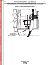
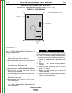
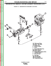
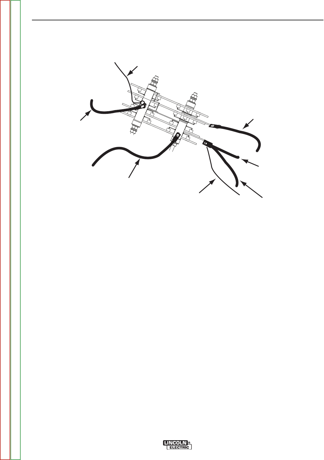
TO POLARITY SWITCH (S2)
LEAD 8
TO CHOKE
(L1)
LEAD 254
TO STATOR (LEAD W1)
TO STATOR (LEAD S2)
TO RANGE SWITCH (S1)
AC2
AC1
FIGURE F.11 – OUTPUT RECTIFIER
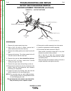
OUTPUT RECTIFIER BRIDGE REMOVAL
AND REPLACEMENT PROCEDURE (continued)
PROCEDURE
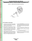
1. Remove the engine spark plug wires.
2. With a 5/16” nut driver or socket, remove the 6
sheet metal screws from the case top.
3. Remove the rubber gasket (cover seal) from the lift
bail.
4. Remove the fuel cap. The rubber gasket for the fill
tube will come off with the case top.
5. Remove the case top, then reinstall the fuel cap.
6. With the 5/16” nut driver, remove the 5 screws
holding the right case side.
7. Remove the right case side by lifting up and out.
8. Disconnect the leads from the four terminals of the
rectifier. Note the lead placement and hardware
positioning for reassembly.
9. Loosen the three (3) mounting nuts that hold the
rectifier assembly to the mounting bracket.
NOTE: The mounting nuts are metric (M8) hardware.
Use the proper wrench or an adjustable wrench
to avoid damaging the nuts.
Do not loosen the nuts closest to the heat sinks.
They are factory set to a specific torque.
10. Remove the rectifier assembly from the bracket.
11. Install the replacement rectifier assembly.
12. Re-connect the leads removed in Step 8.
Clean rectifier connection areas with a “very fine”
abrasive to provide a shiny surface.
Use a thin film of heat sink compound (Dow
Corning 340) between the leads and the rectifier
connection points.
Place the leads and hardware exactly as found on
original installation and tighten securely.
TROUBLESHOOTING AND REPAIR
F-46 F-46
RANGER® 3 PHASE
Return to Section TOC Return to Section TOC Return to Section TOC Return to Section TOC
Return to Master TOC Return to Master TOC Return to Master TOC Return to Master TOC