


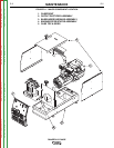

THEORY OF OPERATION
E-3 E-3
RANGER® 3 PHASE
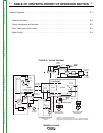
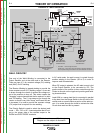
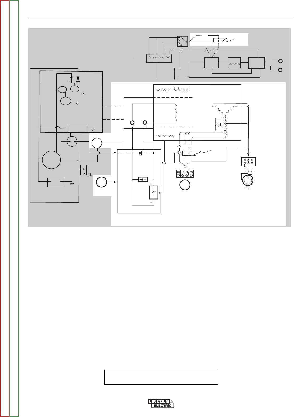
FIGURE E.2 - ROTOR, STATOR AND CONTROL CIRCUITS
NOTE: Unshaded areas of Block Logic
Diagram are the subject of discussion
IDLER
SOLENOID
OUTPUT
CONTROL
MECHANICAL
ROTATION
FIELD
CAPACITOR
SLIP
RINGS
RANGE
SWITCH
OUTPUT
BRIDGE
CHOKE
AC
AC
WORK
TERMINAL
PRINTED CIRCUIT
BOARD
TOROIDTOROID**
ENGINE
FLYWHEEL ALTERNATOR/
VOLTAGE REGULATOR
BATTERY
HOUR
METER
OIL
PRESSURE
SWITCH
+
-
STARTER
FUEL
SHUTOFF
SOLENOID
STARTER
SOLENOID
ENGINE
CONTROL
SWITCH*
4
3
2
1
ZY
3
5
6
X
120 & 230 VOLT
BREAKERS AND
RECEPTACLES
EXCITER
WINDING
AUXILIARY
WINDINGS
WELD WINDINGS
Z X Y
480 VOLT 3 PHASE
BREAKER AND
RECEPTACLE
W2
C1
W1
TOROIDTOROID**
254
3 6 X
*
Lead 254 - 1 turn through the toroid
Leads 3 & 6 - two turns through the toroid in opposite directions.
Lead X passes though the toroid in the same direction as lead 6
STATOR
+
--
ELECTRODE
TERMINAL
POLARITY
SWITCH
ROTOR
FLASHING
DIODE
E
S2
WAC
REACTOR
7 9
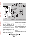
ROTOR, STATOR & CONTROL CIRCUITS
Once the Engine is running and the oil pressure switch
closes, 12 VDC is fed to the rotor slip rings by way of
the Control PC Board. This “flashing” voltage energizes
the rotor and the resulting spinning magnetic field
induces power into the windings of the stator. The
exciter winding voltage is routed to the Control Board
where it is rectified and regulated and fed back to the
rotor slip rings. . This regulated supply is used to control
the voltage output of the welder. A diode on the PC
Board is used to isolate the exciter voltage from the
engine 12 VDC supply. The Output Control is used to
adjust the weld voltage.
The Idler Circuit is also controlled by the Control PC
Board. A Toroid is used to sense current draw through
either the weld circuit or any of the auxiliary receptacles.
When current is sensed, a signal from the Toroid caus-
es the PC Board to release the Idler Solenoid and the
engine goes to high speed.
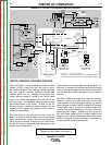
Approximately 10 seconds after the current stops, the
board will re-energize the solenoid and pull the engine
down to the low idle speed. If the Control Power Switch
is in the High Idle position, the signal from the Toroid is
ignored.
The Weld Winding provides the power for welding.
Different portions are used depending on the weld
mode selected. The full winding is used for DC welding
while a tapped off portion (WAC) is used for AC welding.
There is also a tap (C1) used for constant voltage (CV)
welding. The Auxiliary Winding is a 3 phase ‘wye’ con-
nected 480 VAC supply. Tapped off of one leg are the
230 VAC single phase and the 120VAC single phase
supplies for the various receptacles. Each of the recep-
tacles including the 3 phase receptacle is protected by
an appropriately sized Circuit Breaker.
Return to Section TOC Return to Section TOC Return to Section TOC Return to Section TOC
Return to Master TOC Return to Master TOC Return to Master TOC Return to Master TOC