


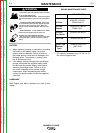

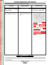
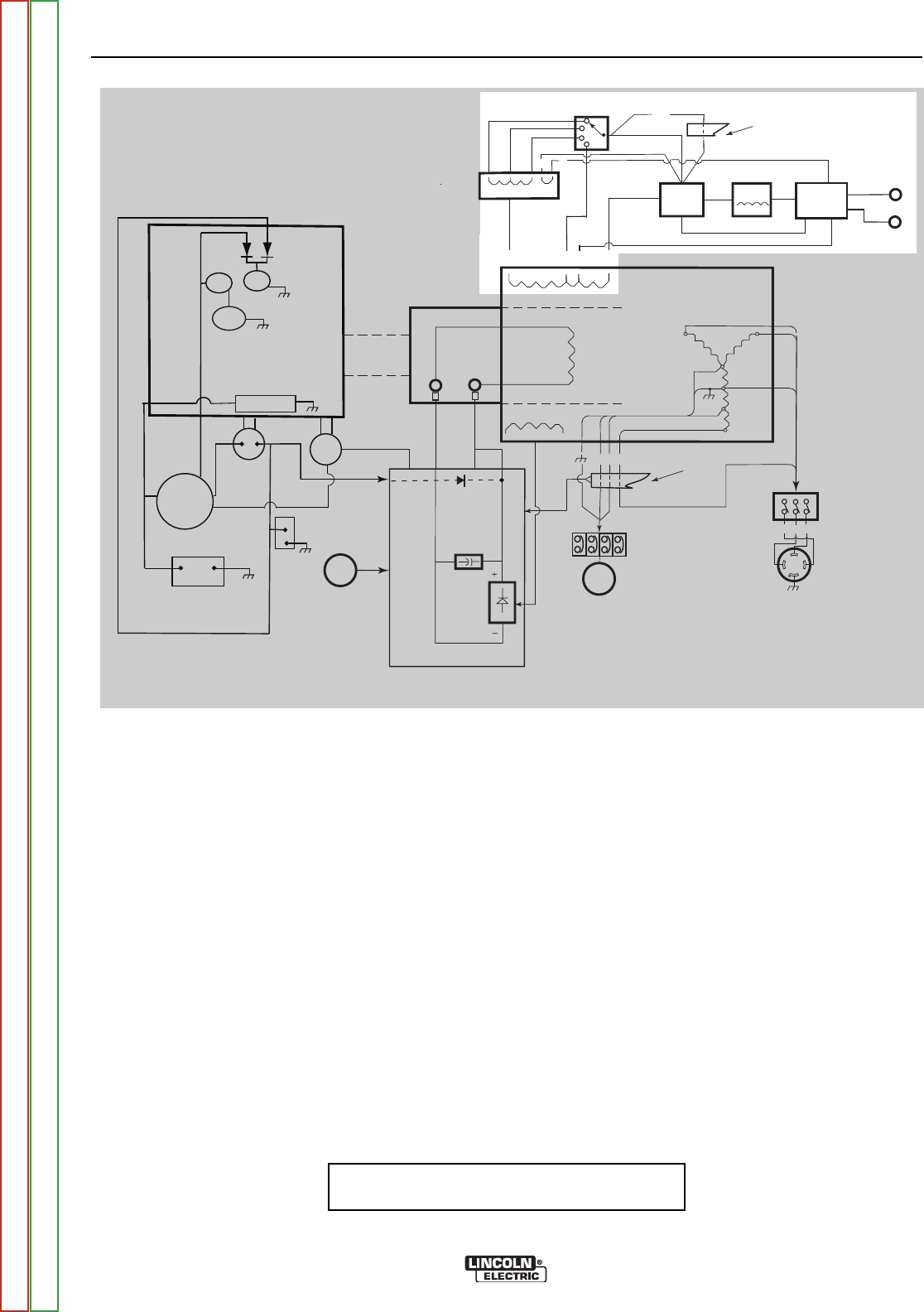
THEORY OF OPERATION
E-4 E-4
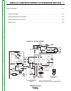
RANGER® 3 PHASE
FIGURE E.2 - WELD CIRCUITRY
NOTE: Unshaded areas of Block Logic
Diagram are the subject of discussion
WELD CIRCUITRY
One end of the Weld Winding is connected to the
Output Rectifier and at the other end to the Reactor.
There are taps (C1) for constant voltage (CV) welding
and (WAC) for AC welding.
The Reactor Winding is tapped winding to provide the
three constant current (CC) welding ranges. As current
is drawn through the reactor it causes the voltage out-
put of the machine to drop off. This action creates the
“drooping” output characteristic that is required for stick
and TIG welding. The C1 tap does not go through the
reactor so there is very little “droop” as the weld current
is increased. It is used to provide the constant voltage
(CV) output that is required for wire welding.
The Polarity Switch is used to select the desired weld
mode — DC+, DC- or AC. It connects either the AC out-
put or the proper side of the rectified output to the
WORK and ELECTRODE terminals.
In AC weld mode, the weld current is routed through
another winding in the Reactor (S2 to E) in order to
improve weld characteristics.
When DC output is selected, the AC weld current is fed
to the Output Rectifier to be converted to DC. The
positve output of the rectifier is then routed through the
Choke to smooth out the ripple and provide good weld-
ing characteristics.
Lead #254 is a sense lead that is connected in parallel
to the lead from the Range Switch to the AC side of the
rectifier and as a result shares a portion of the weld cur-
rent. It is routed through the toroid to activate the Idler
Circuit when weld current is present.
IDLER
SOLENOID
OUTPUT
CONTROL
MECHANICAL
ROTATION
FIELD
CAPACITOR
SLIP
RINGS
RANGE
SWITCH
OUTPUT
BRIDGE
CHOKE
AC
AC
WORK
TERMINAL
PRINTED CIRCUIT
BOARD
TOROIDTOROID**
ENGINE
FLYWHEEL ALTERNATOR/
VOLTAGE REGULATOR
BATTERY
HOUR
METER
OIL
PRESSURE
SWITCH
+
-
STARTER
FUEL
SHUTOFF
SOLENOID
STARTER
SOLENOID
ENGINE
CONTROL
SWITCH*
4
3
2
1
ZY
3
5
6
X
120 & 230 VOLT
BREAKERS AND
RECEPTACLES
EXCITER
WINDING
AUXILIARY
WINDINGS
WELD WINDINGS
Z X Y
480 VOLT 3 PHASE
BREAKER AND
RECEPTACLE
W2
C1
W1
TOROIDTOROID**
254
3 6 X
*
Lead 254 - 1 turn through the toroid
Leads 3 & 6 - two turns through the toroid in opposite directions.
Lead X passes though the toroid in the same direction as lead 6
STATOR
+
--
ELECTRODE
TERMINAL
POLARITY
SWITCH
ROTOR
FLASHING
DIODE
E
S2
WAC
REACTOR
7 9
Return to Section TOC Return to Section TOC Return to Section TOC Return to Section TOC
Return to Master TOC Return to Master TOC Return to Master TOC Return to Master TOC