


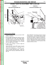
B
A
D
C
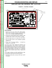
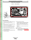
CONTROL
L12198-1
X4
DZ5
D1
C24
C39
R4
D2
X3
C31
R33
R76
R95
R82
R39
Q3
R47
C12
R72
R67
C37
R88
R45
J2
R48
D3
C30
C32
DZ8
D11
D10
C2
R5
TP2
D21
R73
D9
DZ2
DZ10
R11
Q1
R16
DZ9
R10
Q5
R52
R83
R57
D19
R12
C40
C41
R79
C36
R81
R29
R89
R41
DZ4
R84
R80
Q4
R21
R32
R96
C14
R91R40
C26
R20
R85
R69
C10
C13
R17
R23
C1
R44
D16
X1
R58
R42
R75
R49
D14
C29
R43
DZ7
C38
TP1
D15
R7
R94
DZ1
J1
C23
X5
DZ3
R31
C3
R66
R51
C35
R62
R70
D28
R100
DZ11
R19
B1
C43
R13
C27
R34
D18
R14
C28
R15
R56
R102
R97
R18
C4
C42
R46
R101
R74
R65
B2
R87
D4
R98
Q6
C22
R53
R99
R77
R68
R78
C19
R71
C7
FTP1
16
7 12
1
2
3
4
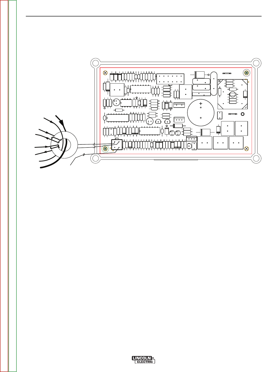
LEAD ‘X’
LEAD 254
LEAD 6
LEAD 3
LEAD 213A
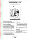
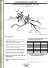
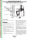
FIGURE F.6 – TOROID ASSEMBLY
TOROID TEST (continued)
TEST PROCEDURE
1. With a 5/16” nut driver or socket, remove the 6
sheet metal screws from the case top.
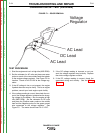
2. Remove the rubber gasket (cover seal) from the lift
bail.
3. Remove the fuel cap. The rubber gasket for the fill
tube will come off with the case top.
4. Remove the case top, then replace the fuel cap.
5. Remove the screws holding the right case side.
6. Remove the right case side by lifting up and out.
7. Start the engine and set it to AUTO and wait for it to
drop to low idle (2400 rpm).
8. Plug a trouble light with a 100 watt bulb into one of
the 120VAC receptacles.
The machine should go to High Idle.
If it does not, measure the voltage across the toroid
leads (260 and 261) at pins 3 and 4 of J2. See
Figure F.6. It should be approximately 2.8VAC.
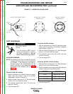
If the voltage is correct, the Control Board may be
defective.
If the voltage is not correct, the toroid may be
defective.
9. Shut the engine OFF.
NOTE: If the Toroid needs to be replaced, pay close
attention to the direction that the various leads
are routed through it. See the Wiring Diagram
for exact instructions.
TROUBLESHOOTING AND REPAIR
F-22 F-22
RANGER® 3 PHASE
Return to Section TOC Return to Section TOC Return to Section TOC Return to Section TOC
Return to Master TOC Return to Master TOC Return to Master TOC Return to Master TOC