


OUTPUT PROBLEMS
Observe Safety Guidelines detailed in the beginning of this manual.
PROBLEMS
(SYMPTOMS)
POSSIBLE AREAS OF
MISADJUSTMENT(S)
RECOMMENDED
COURSE OF ACTION
If for any reason you do not understand the test procedures or are unable to perform the tests/repairs safely,
contact the Lincoln Electric Service Department for technical troubleshooting assistance before you proceed.
Call 1-888-935-3877.
CAUTION
Major Physical or Electrical
Damage is Evident.
1. Contact The Lincoln Electric
Service Dept. 1-888-935-3877.
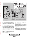
No weld output and no auxiliary
power. Engine runs normally.
1. Check the brushes for wear and
proper contact to the rotor slip
rings.
1. Check for the presence of 12
VDC (at the pc board) from lead
#224 to frame ground. This is
the supply voltage to the board
and is present when the engine
is running and the S3 switch is
in the “HIGH” or “AUTO” posi-
tion. If the 12VDC is missing
check the leads, switches and
connections associated with the
lead #224. See the Wiring
Diagram.
2. Perform the Rotor Voltage
Test.
3. If Rotor Voltage Test is normal,
then preform the Rotor
Resistance Test.
4. If the Rotor Voltage Test is NOT
normal, perform the Auxiliary
and Field Winding Voltage
Test. The Printed Circuit Board
may be faulty. Replace
TROUBLESHOOTING AND REPAIR
F-4 F-4
RANGER® 3 PHASE
Return to Section TOC Return to Section TOC Return to Section TOC Return to Section TOC
Return to Master TOC Return to Master TOC Return to Master TOC Return to Master TOC