


SECTION
2-
INTRODUCTION
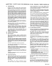
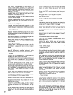
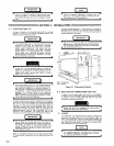
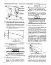
Rated
Amperes
Output
Welding
Current
Range
Welding
Current
Ranges
In
Amperes
Open-Circuit
Voltage
Range
Power
Dimensions
(Inches)
Weight
(Pounds)
?~i~E
1520
1560
~.
Coarse
Ranges
Fine
Range
350
@
40V
100%
Duty
Cycle
45
To
475
Amps
45-
85
65-140
100-220
130
.
300
220
-475
From
Mm.
To
Max.
Of
Each
Coarse
Range
55
To
90
DC
Volts
3kva
120
Volts
AC
50/60
Hz.
While
Welding
7.5
kva
120/240
Volts
AC
50/60
Hz.
As
Power
Plant
Height
-
43-1/2
Width
-25
Depth
-
63
Figure
2-1.
Specifications
TB.007
956
2-1.
GENERAL
This
manual
has
been
prepared
especially
for
use
in
familiar
izing
personnel
with
the
design,
installation,
operation,
main
tenance,
and
troubleshooting
of
this
equipment.
All
informa
tion
presented
herein
should
be
given
careful
consideration
to
assure
optimum
performance
of
this
equipment.
2-2.
RECEIVING-HANDLING
Prior
to
installing
this
equipment,
clean
all
packing
material
from
around
the
unit
and
carefully
inspect
for
any
damage
that
may
have
occurred
during
shipment.
Any
claims
for
loss
or
damage
that
may
have
occurred
in
transit
must
be
filed
by
the
purchaser
with
the
carrier.
A
copy
of
the
bill
of
lading
and
freight
bill
will
be
furnished
by
the
carrier
on
request
if
occasion
to
file
claim
arises.
When
requesting
information
concerning
this
equipment,
it
is
essential
that
Model
Description
and/or
Stock
Number
and
Serial
(or
Style)
Numbers
of
the
equipment
be
supplied.
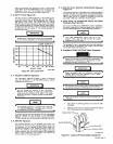
2-3.
DESCRIPTION
This
welding
generator
is
driven
by
a
gasoline
engine.
The
Unit
will
produce
a
dc
output
for
Shielded
Metal
Arc
(SMAW)
Welding
when
used
as
a
welding
generator,
or
an
ac
output
of
7.5
kva
at
120/240
volts
when
used
as
a
power
generator.
A
duplex
receptacle
on
the
front
panel
provides
an
ac
output
of
up
to
3
kva
at
120
volts
to
power
toolt,
lights,
etc.,
while
welding.
This
welding
generator
has
reconnectable
capability
to
provide
240
volts
ac
auxiliary
power
at
the
front
panel
if
the
optional
receptacle
kit
is
ordered.
Should
preparation
and
installation
(or
information
if
factory
installed)
be
desired,
see
Section
5-9
for
complete
instructions,
and
delete
all
reference
to
120
volts
ac
duplex
receptacle
and
replace
with
240
volts
dc
duplex
receptacle.
2-4.
SAFETY
Before
the
equipment
is
put
into
operation,
the
safety
sec
tion
at
the
front
of
this
manual
should
be
read
completely.
This
will
help
avoid
possible
injury
due
to
misuse
or
improper
welding
applications.
The
following
definitions
apply
to
CAUTION.
IMPORTANT.
and
NOTE
blocks
found
throughout
this
manual:
CAUTION
Under
this
heading,
installation,
oper~g,
and
main
tenance
procedures
or
practices
will
be
found
that
if
not
carefully
followed
may
create
a
hazard
to
per
sonnel.
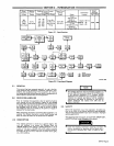
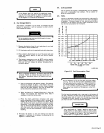
Figure
2-2.
Functional
Diagram
m
OM-457
Page
5