


SECTION
7-
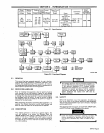
SEQUENCE
OF
OPERATION
EAr1
Make
sure
all
electrical
equipment
connected
to
the
120
VOLTS
AC
receptacle
and
120/240
volts
ac
ter
minal
strip
is
turned
off
before
starting
the
engine.
The
engine,
when
starting,
has
low
rpm
which
causes
low
voltage
at
the
output
receptacle
of
the
generator.
This
could
result
in
damage
to
electrical
equipment.
1.
Ensure
that
the
engine
has
been
prepared
for
operation
as
instructed
in
Section
4.
2.
Make
connections
to
the
120/240
volts
ac
terminals
as
instructed
in
Section
3-5.
3.
Rotate
the
FINE
AMPERAGE
control
to
the
100
(full
counterclockwise)
setting.
4.
Start
the
engine
as
instructed
in
Section
7-3.
5.
Place
the
IDLE
CONTROL
switch
in
the
LOCK
OUT
position
and
commence
operation.
7-3.
STARTING
THE
ENGINE
IMPORTANT
Check
the
engine
oil
level
and
radiator
coolant
level.
Make
sure
no
loose
parts
etc.
are
laying
in
the
unit.
Make
the
ne~ssary
connections
to
the
generator
before
attempting
to
start
the
unit.
Fill
the
fuel
tank
with
fresh
gasoline.
1.
Make
all
welding
and
electrical
connections
to
the
welding
generator.
2.
Place
the
IDLE
CONTROL
switch
in
the
AUTOMATIC
IDLE
position.
This
should
be
done
in
order
to
permit
the
engine
to
warm
up
at
idle
rpm.
3.
Choke
the
engine
as
necessary.
4.
Rotate
the
Ignition
switch
to
the
RUN
position.
5.
Press
the
START
push
button.
4.
Rotate
the
FINE
AMPERAGE
control
to
the
desired
setting.
5.
If
a
Remote
Amperage
Control
is
not
to
be
used, place
the
REMOTE
AMPERAGE
CONTROL
switch
in
the
STANDARD
position.
If
a
Remote
Amperage
Control
is
to
be
used,
place
the
REMOTE
AMPERAGE
CONTROL
switch
in
the
REMOTE
position.
6.
Start
the
engine
as
instructed
in
Section
7-3.
7.
Place
the
IDLE
CONTROL
switch
in
the
desired
position
and
commence
welding.
8.
The
FINE
AMPERAGE
control
(or
remote
amperage
control
if
used)
may
be
adjusted
while
welding.
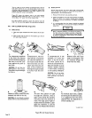
Always
ensure
that
the
starter
pinion
and
flywheel
h~e
stopped
rotating
before
re-engaging
the
starter
motor,
otherwise
the
ring
or
pinion
may
be
damaged.
6.
When
the
engine
Starts,
release
the
START
push
button.
As
the
engine
warms
up,
slowly
push
the
CHOKE
in.
7.4.
ENGINE
SHUT
DOWN
1.
Remove
all
weld
and
power
loads
from
the
generator.
2.
Allow
the
engine
to
idle
for
a
few
minutes,
allow
a
longer
length
of
time
if
the
engine
has
been
operating
at
full
load.
This
idling
time
is
to
ensure
that
the
intemal
engine
temperature
has
a
chance
to
equalize.
I
Make
sure
~
IMPORTANT
all
electrical
equipment
connected
to
the
120
VOLTS
AC
receptacle
and
120/240
volts
ac
ter
minal
strip
is
turned
off
before
starting
the
engine.
The
engine,
when
starting,
has
low
rpm
which
causes
low
voltage
at
the
output
receptacle
of
the
generator.
This
could
result
in
damage
to
electrical
equipment.
IMPORTANT
Do
not
operate
accessory
power
equipment
from
the
120
VOLTS
AC
receptacle
or
120/240
volts
terminals
during
the
engine
shutdown-idling
period.
3.
Place
the
Ignition
switch
in
the
OFF
position.
CAUTION
I
Never
under
any
circumstances,
ope~he
welding
generator
with
any
portion
of
the
outer
enclosure
open
or
removed.
In
addition
to
being
a
hazard
to
personnel,
weather
protection
to
the
internal
com
ponents
of the
unit
will
be
greatly
reduced.
Warranty
is
void
if
the
welding
generator
is
operated
with
any
portion
of
the
outer
enclosure
open
or
removed.
7-1.
SHIELDED
METAL-ARC
(SMAW)
WELDING
I
I
Prior
to
welding,
it
is
imperative
that
proper
protective
clothing
(welding
coat
and
gloves)
and
eye
protection
(glasses
and/or
welding
helmet)
be
put
on.
Failure
to
comply
may
result
in
serious
or
permanent
bodily
damage.
-
_________________________
1.
Ensure
that
the
engine
has
been
prepared
as
instructed
in
Section
4.
2.
Make
Connections
to
the
weld
output
terminals
as
re
quired.
3.
Place
the
Ignition
switch
in
the
OFF
position.
IMPORTANT
I
I
7-2.
POWER
PLANT
OPERATION
OM-457
Page
13