


A
See
Figure
9-4
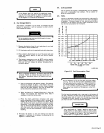
9-9.
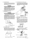
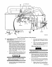
IDLE
CONTROL/GOVERNOR
LINKAGE
ADJUST
MENT
(Figure
9-7)
in
the
event
that
proper
engine
idle
and/or
weld
rpm
is
not
being
attained,
perform
the
following
procedures
to
calibrate
the
engine
for
proper
idle
and
weld
rpm:
1.
Adjust
the
length
of
the
governor
linkage
(item
1,
Figure
9-7)
so
that
the
throttle
stop
plate
(2)
is
about
1/32
from
the
stop
(3).
To
adjust
the
linkage
(1),
loosen
the
linkage
securing
nuts
(5)
and
remove
the
hardware
(6)
securing
the
linkage
socket(s)
(4)
to
the
governor
and
carburetor.
Rotate
the
linkage
socket(s)
(4)
accordingly
to
obtain
the
1/32
gap.
Clockwise
rotation
of
the
linkage
socket(s)
)4(
will
shorten
the
governor
linkage
(1)
and
thus
reduce
the
gap.
Con
versely,
counterclockwise
rotation
of
the
linkage
socket)s)
(4)
will
lengthen
the
governor
linkage
)1)
and
thus
increase
the
gap.
2.
Rotate
the
linkage
socket(s)
)4)
slightly
until
the
sockets
(4)
are
parallel
but
in
opposite
directions
with
respect
to
each
other.
Secure
the
linkage
socket
nuts
(5)
to
lock
the
position
of
the
linkage
socket(s)
(4).
~thelinkage~edomofmovement
throughout
its
entire
travel.
If
the
linkage
)1)
is
bind
ing
due
to
the
linkage
socket(s)
(4)
being
cocked
relative
to
each
other,
repeat
Step
2.
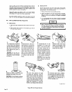
A.
Position
the
arm
(8)
laterally
so
that
the
carbur
etor
linkage
socket
(4)
does
not
touch
the
throttle
stop
plate
(2)
throughout
its
entire
travel.
B.
Position
the
arm
(8)
radially
so
that
the
arm
(8)
travels
an
equal
distance
to
either
side
of
an
imaginary
center
line
drawn
perpendicular
to
the
center
of
the
throttle
shaft
(9).
Tighten
the
alignment
screw
(7)
and
recheck
the
ad
justments
made
in
Steps
1
and
2.
sta
rti~7
t
he
e
ngine
and
while
wo
r
ki
ng
on
t
he
engine,
ensure
that
body
limbs
are
clear
of
the
fan
and
of
the
vacuum
motor
unit.
4.
Recheck
all
connections
made
thus
far.
Place
the
IDLE
CONTROL
switch
in
the
LOCK
OUT
position.
Start
the
welding
generator
engine
and
allow
the
engine
to
reach
normal
operating
temperature
(about
five
minutes).
Ensure
that
the
CHOKE
control
is
push
ed
fully
in
at
this
time.
5.
Pull
the
arm
(8)
toward
the
front
of
the
welding
gener
ator
to
the
idle
position.
Maintain
pressure
on
the
arm
(8)
to
butt
the
idle
screw
(10)
against
the
stop
(3)
throughout
the
following
adjustments:
A.
Rotate
the
idle
screw
(10)
to
obtain
400
rpm.
Clockwise
rotation
of
the
screw
(10)
will
in
crease
engine
rpm
whereas
counterclockwise
(2
1
'
10
~
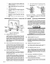
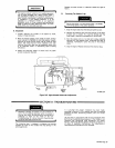
Figure
9-7.
Idle
Control/Governor
Linkage
Adjustment
TC-003
226
I
I
3.
Loosen
the
alignment
screw
(7)
and
position
the
arm
(8)
radially
and
laterally
until
the
following
conditions
are
simultaneously
met:
OM-457
Page
17