


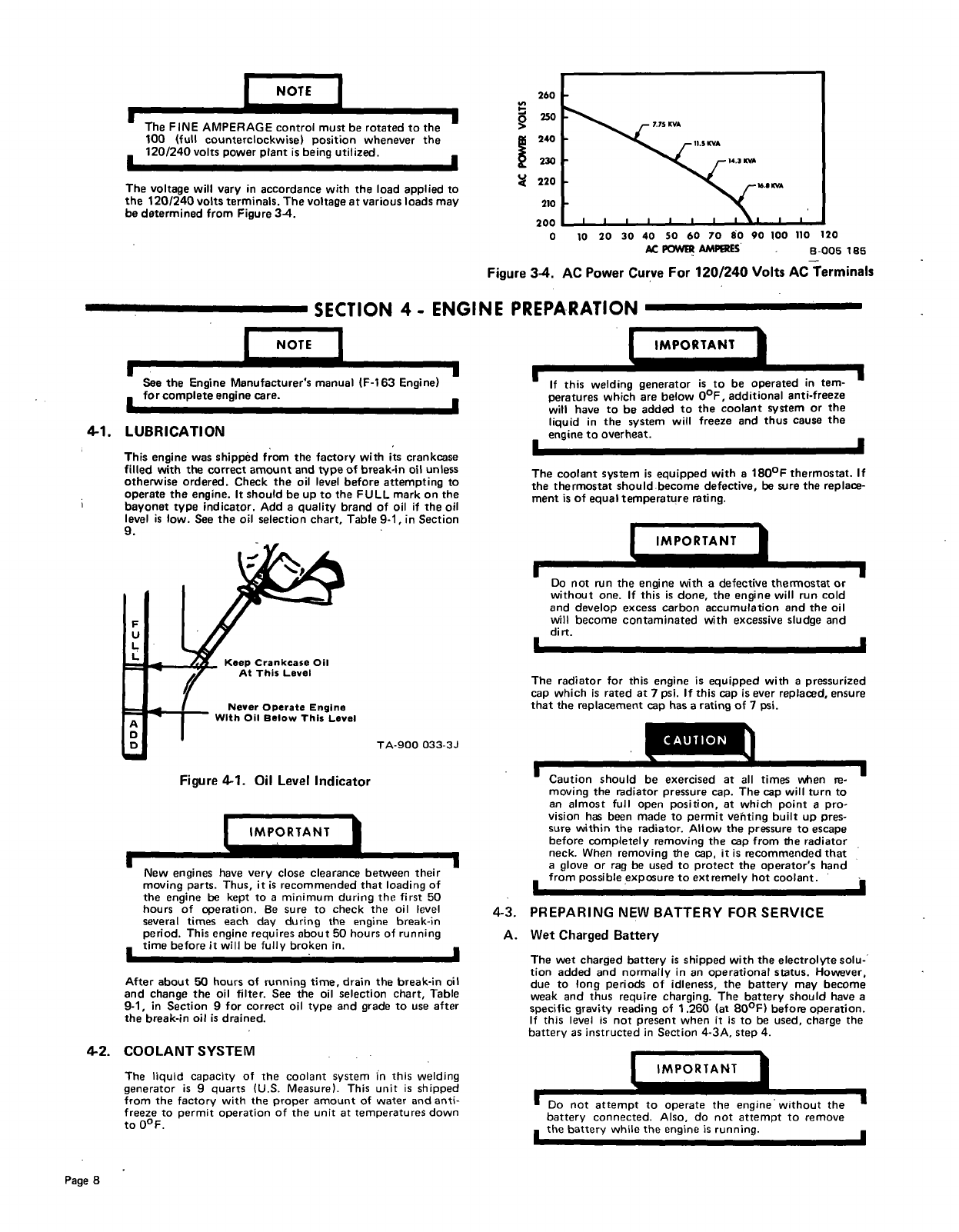
Figure
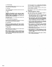
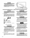
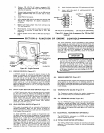
3-4.
AC
Power
Curve
For
120/240
Volts
AC
Terminals
SECTION
4
-
ENGINE
PREPARATION
1
Fl
F
I
See
the
Engine
Manufacturers
manual
(F-i
63
Engine)
for
complete
engine
care.
4-1.
LUBRICATION
This
engine
was
shippAd
from
the
factory
with
its
crankcase
filled
with
the
correct
amount
and
type
of
break-in
oil
unless
otherwise
ordered.
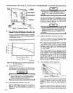
Check
the
oil
level
before
attempting
to
operate
the
engine.
It
should
be
up
to
the
FULL
mark
on
the
bayonet
type
indicator.
Add
a
quality
brand
of
oil
if
the
oil
level
is
low.
See
the
oil
selection
chart,
Table
9-1,
in
Section
9.
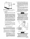
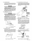
Figure
4-1.
Oil
Level
Indicator
L–~RTANT~
I
New
engines
have
very
close
clearance
between
their
moving
parts.
Thus,
it
is
recommended
that
loading
of
the
engine
be
kept
to
a
minimum
during
the
first
50
hours
of
operation.
Be
sure
to
check
the
oil
level
several
times
each
day
during
the
engine
break-in
period.
This
engine
requires
about
50
hours
of
running
time
before
it
will
be
fully
broken
in.
After
about
50
hours
of
running
time,
drain
the
break-in
oil
and
change
the
oil
filter.
See
the
oil
selection
chart,
Table
9-1,
in
Section
9
for
correct
oil
type
and
grade
to
use
after
the
break-in
oil
is
drained.
The
liquid
capacity
of
the
coolant
system
in
this
welding
generator
is
9
quarts
(U.S.
Measure).
This
unit
is
shipped
from
the
factory
with
the
proper
amount
of
water
and
anti
freeze
to
permit
operation
of
the
unit
at
temperatures
down
to
0F.
I
. .
~i~RTANTI
-
1
If
this
welding
generator
is
to
be
operated
in
tem
peratures
which
are
below
0F,
additional
anti-freeze
will
have
to
be
added
to
the
coolant
system
or
the
liquid
in
the
system
will
freeze
and
thus
cause
the
engine
to
overheat.
I
I
The
coolant
system
is
equipped
with
a
180F
thermostat.
If
the
thermostat
should-become
defective,
be
sure
the
replace
ment
is
of
equal
temperature
rating.
Do
not
run
the
engine
with
a
defective
thermostat
or
without
one.
If
this
is
done,
the
engine
will
run
cold
and
develop
excess
carbon
accumulation
and
the
oil
will
become
contaminated
with
excessive
sludge
and
dirt.
I
The
radiator
for
this
engine
is
equipped
with
a
pressurized
cap
which
is
rated
at
7
psi.
If
this
cap
is
ever
replaced,
ensure
that
the
replacement
cap
has
a
rating
of
7
psi.
~on
a
hou
Id
be
ax
ercised
at
all
times
wi~en
re
moving
the
radiator
pressure
cap.
The
cap
will
turn
to
an
almost
full
open
position,
at
which
point
a
pro
vision
has
been
made
to
permit
veuiting
built
up
pres
sure
within
the
radiator.
Allow
the
pressure
to
escape
before
completely
removing
the
cap
from
the
radiator
neck.
When
removing
the
cap,
it
is
recommended
that
-
a
glove
or
rag
be
used
to
protect
the
operators
hand
from
possible
exposure
to
extremely
hot
coolant.
PREPARING
NEW
BATTERY
FOR
SERVICE
Wet
Charged
Battery
The
wet
charged
battery
is
shipped
with
the
electrolyte
solu
tion
added
and
normally
in
an
operational
status.
However,
due
to
long
periods
of
idleness,
the
battery
may
become
weak
and
thus
require
charging.
The
battery
should
have
a
specific
gravity
reading
of
1.260
(at
80F)
before
operation.
If
this
level
is
not
present
when
it
is
to
be
used,
charge
the
battery
as
instructed
in
Section
4-3A,
step
4.
m
I
I
The
FINE
AMPERAGE
control
must
be
rotated
to
the
100
(full
counterclockwise)
position
whenever
the
120/240
volts
power
plant
is
being
utilized.
I
I
The
voltage
will
vary
in
accordance
with
the
load
applied
to
the
120/240
volts
terminals.
The
voltage
at
various
loads
may
be
determined
from
Figure
3-4.
260
U,
250
7.7SKVA
I.SKVA
240
230
14.3
KVA
~
220
~
16.1
KVA
210
200
0
10
20
30
40 50
60
70
80
90
100
110
120
~
POWER
.MPERES
8-005
185
Keep
Crankcase
Oil
At
This
Level
U
Never
Operate
Engine
With
Oil
Below
This
Level
TA-900
033-3.1
I
I
4-3.
A.
4-2.
COOLANT
SYSTEM
IMPORTANT
Do
not
attempt
to
operate
the
engine
without
the
battery
connected.
Also,
do
not
attempt
to
remove
the
battery
while
the
engine
is
running.
Page
8