


show
the
minimum
and
maximum
curves
of
each
coarse
range.
When
the
FINE
AMPERAGE
control
is
adjusted,
the
volt-ampere
curve
will
fall
between
the
minimum
and
maximum
curves
of
the
particular
coarse
range
in
use.
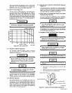
5
-
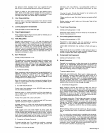
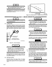
6.
DUTY
CYCLE
(Figure
54)
The
duty
cycle
of
a
welding
generator
is
the
percentage
of
a
ten
minute
period
that
a
welding
generator
can
safely
be
operated
at
a
given
output.
This
welding
generator
is
rated
at
100
percent
duty
cycle.
This
means
that
the
welding
generator
can
be
safely
operated
at
rated
load
continuously.
If
the
welding
amperes
are
increased
beyond
rated
output,
the
duty
cycle
will
decrease.
Figure
5-4
enables
the
operator
to
determine
the
safe
output
of
the
welding
generator
at
various
duty
cycles.
I
IMPORTANT
Exceeding
the
indicated
duty
cycle
will
cause
damage
to
the
internal
components
of
the
welding
generator.
U
250
RATED
OUTPUTi
-~
;;;
-
~bq~
-
-
-
~%
30
40
50
60
70
80
90
100
%
DUTY
CYCLE
B-053
306
Figure
5-4.
Duty
Cycle
Chart
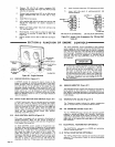
5-
7.
POLARITY
SWITCH
(Optional)
The
POLARITY
SWITCH
provides
a
means
of
selecting
either
DC
STRAIGHT
or
DC
REVERSE
polarity
without
changing
cable
connections.
Do
not
change
the
position
of
the
POLARITY
SWITCH
while
welding
or
under
load,
as
this
causes
arcing
across
the
contacts
of
the
switch.
This
arcing
causes
the
contacts
to
become
pitted
and
eventually
inoperative.
If
the
welding
generator
is
equipped
with
a
POLAR
ITY
SWITCH
(Optional),
the
weld
output
terminals
are
labeled
ELECTRODE
and
WORK.
To
ensure
that
the
weld
current
output
will
be
in
accordance
with
the
labeling
of
the
position
on
the
POLARITY
SWITCH,
connect
the
electrode
holder
cable
to
the
ELEC
TRODE
terminal
and
the
work
cable
to
the
WORK
terminal.
5-
8.
METERS
(Optional)
This
welding
generator
can
be
equipped
with
meters.
The
meters
are
for
monitoring
the
welding
operation
and
serve
as
an
indication
of
the
welding
process.
These
meters
are
internally
connected
to
the
welding
generator
output
ter
minals.
The
voltmeter
will
indicate
the
voltage
at
the
weld
output
terminals,
not
the
actual
voltage
at
the
welding
arc
(due
to
cable
resistance).
The
ammeter
will
indicate
the
current
output
of
the
welding
generator.
5-
9.
240
VOLTS
AC
DUPLEX
RECEPTALCE
(Optional)
(Figure
5-1)
This
welding
generator
is
equipped
with
a
voltage
changeover
terminal
strip
TEl
and
proper
stator
to
provide
reconnection
capbility
for
240
volts
ac.
Although
the
capability
for
either
120
or
240
volts
ac
is
present,
an
optional
kit
must
be
purchased
if
240
volts
is
desired
at
the
front
panel.
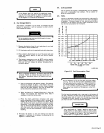
A.
Power
Curve
For
Optional
240
VOLTS
AC
Duplex
Receptacle
(See
Figure
5-2).
Up
to
3
kva
of
240
volts
ac
50/60
Hertz
power
is
available
at
the
duplex
receptacle
for
operating
power
tools,
lights,
etc.,
when
the
welding
generator
is
being
operated
at
weld
rpm.
The
FINE
AMPERAGE
control
may
be
in
any
position
when
using
the
240
VOLTS AC
duplex
receptacle
on
the
front
panel.
I.~
The
voltage
will
vary
in
accordance
with
the
load
applied
to
the
240
VOLTS
AC
receptacle.
The
voltage
at
various
loads
may
be
determined
from
Figure
5-2.
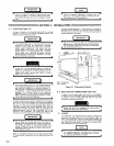
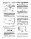
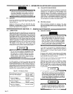
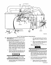
B.
Installation
Of 240
VOLTS
AC
Duplex
Receptacle
Ensure
that
the
engine
is
completely
shut
down
before
attempting
any
connections
or
examination
of
com
ponents
on
or
near
terminal
strip
TEl.
TA~
Before
proceeding
with
this
installation,
familiarize
yourself
with
the
circuit
diagram
in
the
Trouble
shooting
Section
of
this
manual.
NOTE
All
directions,
such
as
left
or
right,
are
with
respect
to
1
the
operator
facing
the
welding
generator
front
panel.
U
NOTE
Retain
all
hardware
removed
during
this
procedure
for
i
installation.
1.
Shut
down
the
welding
generator
and
raise
the
right
I
side
panel.
2.
Remove
center
bolt
from
insulation
board
(see
Figure
5-5),
remove
and
retain
insulation
board.
U
500
~
450
400
4
0
350
z
300
I
I
I
I
I
I
U
Terminal
Strip
TEl.
Duplex
Receptacle
TA-059
485
Figure
5-5.
Location
Of
Reconnectable
Components
tar
Bolt
OM-457
Page
11