


8.
Tighten
the
two
locking
nuts
(13)
to
maintain
the
desired
governor
sensitivity.
Readjust
the
governor
sensitivity
by
repeating
Step
7.
)
1~
Whenever
the
governor
sensitivity
(Step
7)
is
adjusted,
the
governor
speed
(Step
6)
MUST
be
readjusted.
Whenever
the
governor
speed
(Step
61
is
adjusted,
the
governor
sensitivfty
(Step
71
MAY
need
readjustment.
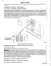
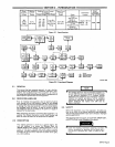
Amend
Section
9-10.
HIGH
ALTITUDE
CARBURETOR
MODIFICATION
(Optional)
(Figure
9-7)
The
Teledyne
Walbro
carburetor
can
be
equipped
with
an
adjustable
main
jet
for
high-altitude
operation
(above
4000
ft.).
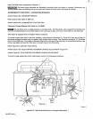
Minor
adjustment
will
be
necessary
for
proper
operation
at
a
particular
altitude.
Whenever
a
carburetor
adjust
ment
is
deemed
necessary,
see
Figure
9-7
and
proceed
as
follows:
Loosen
the
main
adjustment
screw
locking
nut
(22).
Apply
a
near-full
engine
load
to
the
welding
generator.
Rotate
the
main
adjustment
screw
(21)
clockwise
until
the
engine
begins
to
falter
and
lose
RPM.
Rotate
the
main
adjustment
screw
(21)
counterclockwise
until
the
engine
operates
smoothly;
then
continue
counterclockwise
rotation
of
1/4
turn.
Rotating
the
screw
(21)
clockwise
restricts
the
fuel
flow,
making
the
air-fuel
mixture
leaner.
Rotating
the
screw
(21)
counterclockwise
admits
more
fuel,
making
the
air-fuel
mixture
richer.
Remove
the
engine
load.
Tighten
the
locking
nut
(22).
IMPORTANT
Restricting
the
fuel
flow
to
the
point
where
the
mixture
is
too
lean
will-cause
valve
burning.
Delete
Figure
9-8.
High-Altitude
Carburetor
Adjustment
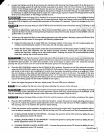
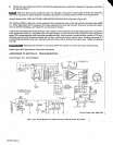
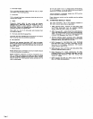
AMENDMENT
TO
SECTION
10
-
TROUBLESHOOTING
C
o~a
UETEA
(Q~T
C%AL)
OM-457C
PageD
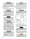
Figure
10-1.
Circuit
Diagram
For
Models
Effective
With
Serial
No.
HJ211479
Amend
Figure
10-1.
Circuit
Diagram
AC
EOWE3
,,_-_~___
5EU~A4~.
GRCcu~UIC
~
S~3ED
E~E1r
*.OTE
~
SIAAA
~
AE
AWE
A1.DWELE!R
jESUS
72
33
r.._77
~
;scfi
-~
~
127
J,~2
24
23
EOW
REAR
VIEW
CAUTION
I
I
I
c0)
~
-~<
CA~.GE-3VER
I
~
~7
I
I
NCI.~C:p~V
acE
~OLr
I
If
-
/
Circuit
Diagram
No.
B-081
027