


CAUTION.:
-
Add
CAUTION
block
at
beginning
of
Section
/
The
weld
output
terminals
are
electrically
energized
when
the
engine
is
running.
Disconnect
the~
we/ding
cables
when
not
we/ding
and
do
not
touch
the
output
terminals
when
the
engine
is
running.
AMENDMENT
TO
SECTION
9-
ENGINE
MAINTENANCE
Amend
Section
9-3.
GOVERNOR
SERVICE
Weld
speed
of
this
engine
is
1850
rpm.
Amend
Section
9-4.
CARBURETOR
FLOAT
SETTING
Carburetor
Change
Effective
With
Serial
No.
HJ185451
I~1t~
Do
not
bend,
twist,
or
apply
pressure
on
the
float
body.
The
float
body,
when
viewed from
the
free
end,
must
be
centered
between
and
at
right
angles
to
the
machined
surface,
and
must
move
freely
on
the
float
axle.
This
engine
is
equipped
with
a
Teledyne
Walbro
carburetor.
To
ensure
correct
fuel
level
in
the
float
chamber,
check
distance
(dimension
A,
Figure
9-1)
from
top
of
float
to
machined
surface
of
throttle
body
(no
gasket)
with
throttle
body
inverted.
This
dimension
should
be
1-1/16
inches
plus
or
minus
.020
inch.
To
increase
or
decrease
distance
from
the
top
of
the
float
body
to
the
machined
surface,
use
a
long
nose
pliers
and
bend
the
float
lever
at
a
point
close
to
the
float
body.
Delete
Figure
9-2.
Carburetor
Float
Setting
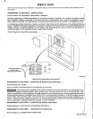
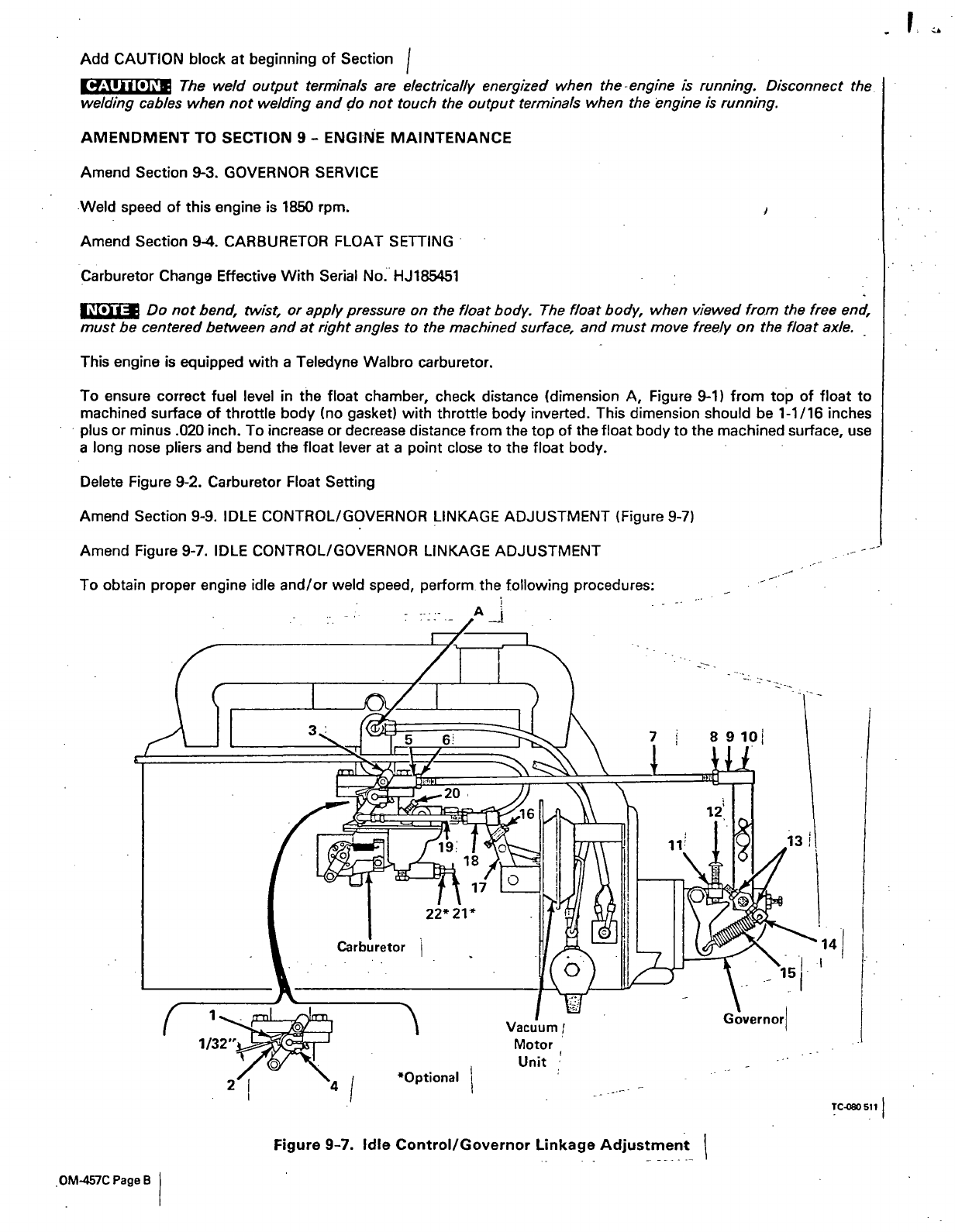
Amend
Section
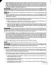
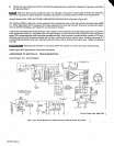
9-9.
IDLE
CONTROL/GOVERNOR
LINKAGE
ADJUSTMENT
(Figure
9-7)
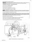
Amend
Figure
9-7.
IDLE
CONTROL/GOVERNOR
LINKAGE
ADJUSTMENT
To
obtain
proper
engine
idle
and/or
weld
speed,
perform~
the
following
procedures:
0M-457C
Page
B
Figure
9-7.
Idle
Control/Governor
Linkage
Adjustment
TCO8O
511