


9-3.
GOVERNOR
SERVICE
The
governor
speed
setting
and
sensitivity
setting
are
factory
set
to
obtain
Correct
weld
rpm
and
engine
response
to
chang
ing
load
conditions.
The
governor
speed
control
setting
is
factory
locked
with
a
lead
seal.
Do
not
remove
this
seal
un
less
absolutely
necessary.
NOTE
The
governor,
as
used
in
conjunction
with
this
engine,
does
not
have
a
No
Load
Surge
adjustment
as
,d~cribed
in
the
Engine
Manual.
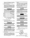
The
engine
is
factory
set
to
operate
at
1200
rpm
idle
speed
and
1800
rpm
when
it
comes
up
to
weld
speed.
For
infornia
tion
concerning
governor
adjustment,
refer
to
the
Engine
Manual,
Page
41,
paragraph
entitled
Pierce
Governor.
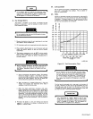
9-4.
CARBURETOR
FLOAT
SETTING
A.
Zenith
Carburetor
NOTE
Do
not
bend,
twist,
or
apply
pressure
on
the
float
bodies.
The
float
bodies
when
viewed
from
the
free
end
of
the
bodies
must
be
centered
between
and
at
right
angles
to
the
machined
surface
and
must
move
freely
on
the
float axle.
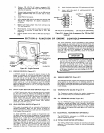
To
ensure
correct
fuel
level
in
the
float
chamber,
check
dis
tance
(dimension
A,
Figure
9-1)
from
top
of
floats
to
machined
surface
of
throttle
body
(no
gasket)
with
throttle
body
inverted.
This
dimension
should
be
1-5/32
inches
plus
or
minus
1/32
inch.
To
increase
or
decrease
distance
from
the
top
of
the
float
bodies
to
the
machined
surface,
use
a
long
nose
pliers
and
bend
the
float
lever
at
a
point
close
to
the
float
body.
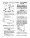
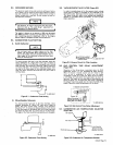
B.
Marvel-Schebler
Carburetor
To
ensure
correct
fuel
level
in
the
float
chamber,
check
distance
(dimension
B,
Figure
9-2)
from
top
of
floats
to
gasket
face
with
throttle
body
inverted.
This
dimension
should be
1/4.
To
increase
or
decrease
distance
from
the
top
of
the
float
bodies
to
the
gasket
face,
use
a
long
nose
pliers
and
bend
the
float
lever
at
a
point
close
to
the
float
body.
The
edge
of
the
float
should
be
kept
parallel
with
the
gasket.
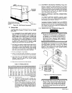
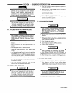
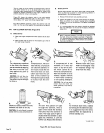
9-5.
VACUUM
CIRCUIT
AIR
FILTER
(Figure
9-3)
In
order
to
provide
clean
air
for
the
vacuum
circuit,
a
brass
fitting
type
air
cleaner
is
provided
on
the
underside
of
the
idle
control
valve.
See
Figure
9-3
for
location
on
the
engine.
This
brass
fitting
will
have
to
be
removed
and
cleaned
in
gasoline
or
a
suitable
solvent
periodicelly
to
ensure
proper
engine
operation.
Figure
9-3.
Vacuum
Circuit
Air
Filter
Location
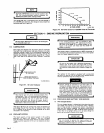
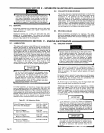
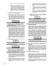
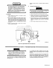
9-6.
IDLE
CONTROL
TIME
DELAY
ADJUSTMENT
(Figure
9-4)
Operation
of
the
idling
device
is
automatic
when
the
IDLE
CONTROL
switch
is
in
the
AUTOMATIC
IDLE
position.
When
the
engine
is
started,
engine
rpm
will
remain
at
idle
until
an
arc
is
established,
at
which
time
the
engine
immediately
comes
up
to
weld
rpm.
When
the
arc
is
broken,
a
time
delay
will
exist
before
the
engine
begins
to
return
to
idle
rpm.
The
length
of
this
time
delay
is
controlled
by
the
setting
of
Screw
A
in
Figure
9-4.
This
screw
is
located
on
the
vacuum
line
fitting
going
into
the
intake
manifold
of
the
engine.
Figure
9-4
shows
the
adjustment
of
this
screw.
In
Engine
Compartment
d
Screw
A
Adjust
Clockwise
1/8
Turn
At
A
Time
To
In-
crease
Idle
Time
Delay.
~
L..
__j
Brass
Fitting
Located
On
Underside
Of
Idle
Control
Valve.
TA-900
955-bA
TA-900
955-7
Figure
9-1.
Carburetor
Float
Setting
TA-gOD
955-3A
Figure
9-4.
Idle
Control
Time
Delay
Adjustment
9-7.
CARBURETOR
AIR
TEMPERATURE
SELECTOR
(Figure
9-5)
Air
Cleaner
Air
Inlet
Selector
(Shown
In
Coid
Manifoid
Stove
Weather
Position)
TA-900
955-4
Figure
9-5.
Carburetor
Air
Temperature
Selector
Figure
9-2.
Carburetor
Float
Setting
TA-008
835
OM-457
Page
15