


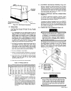
3.
Remove
120
VOLTS
AC
duplex
receptacle
RC1
located
on
front
panel
(see
Figure
5-5).
Remove
leads
and
allow
to
hang
free.
4.
Connect
leads
removed
from
RC1
to
the
240
volts
ac
duplex
receptacle
RC2
(one
on
each
side
of
recep
tacle).
Install
RC2
in
front
panel.
Affix
supplied
240
VOLTS
AC
label
over
existing
120
VOLTS
AC
designation
for
duplex
receptacle
on
nameplate.
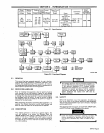
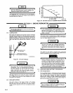
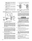
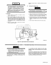
7.
Remove
and
retain
jumper
links
from
terminal
strip
TEl
(see
Figure
5-6).
8.
Move
lead
No.
3
(only
lead
on
jumper
link
side)
from
terminal
B
to
terminal
A
(same
side
of
TEl).
See
Figure
5-6.
9.
Position
jumper
links
on
TEl
for
240
volts
(see
Figure
5-6).
10.
Install
insulation
board
over
TEl
and
secure
with
bolt.
11.
Lower
right
side
panel
of
welding
generator
and
resume
operation.
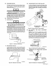
SECTION
6-FUNCTION
OF
ENGINE
CONTROLS
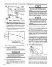
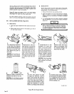
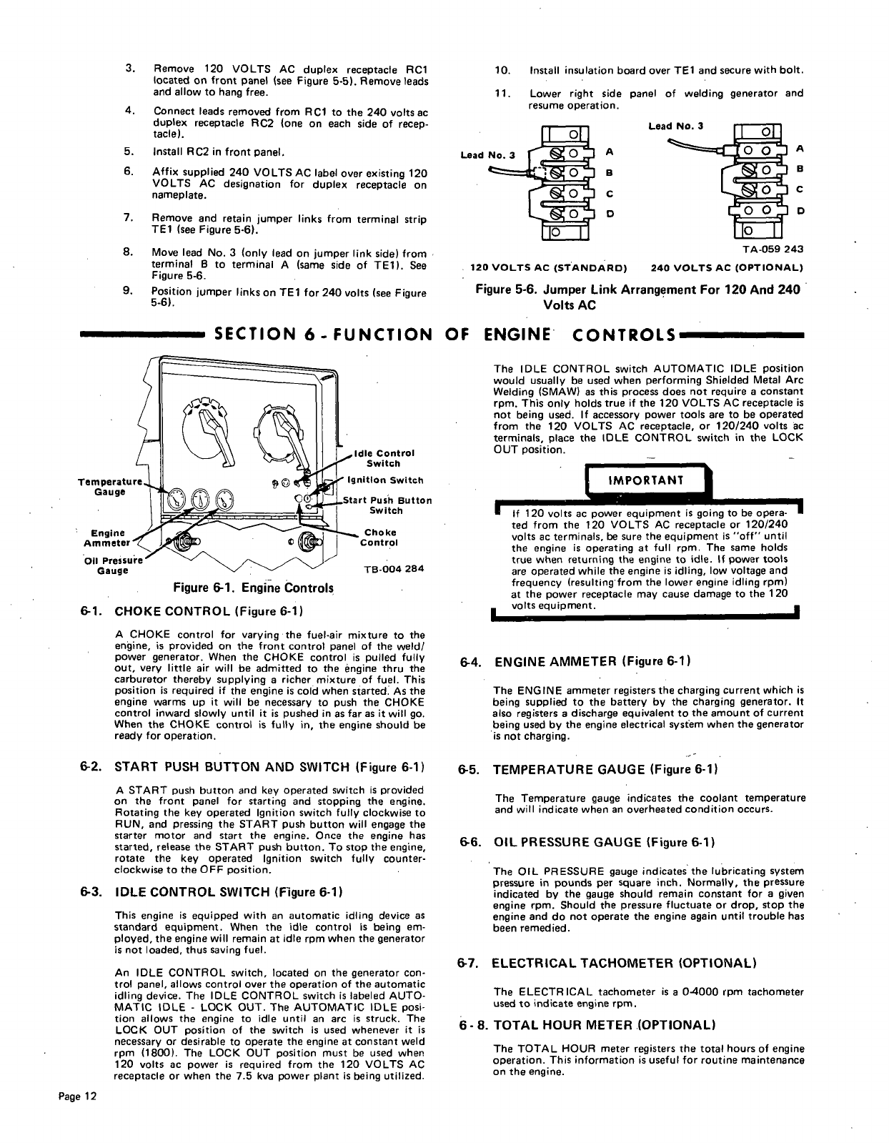
Temperatuu
Gauge
Engine
Ammeter
-
Oil
Pressure
Gauge
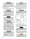
6-1.
CHOKE
CONTROL
(Figure
6-1)
A
CHOKE
control
for
varying
the
fuel-air
mixture
to
the
engine,
is
provided
on
the
front
control
panel
of
the
weld!
power
generator.
When
the
CHOKE
control
is
pulled
fully
out,
very
little
air
will
be
admitted
to
the
engine
thru
the
carburetor
thereby
supplying
a
richer
mixture
of
fuel.
This
position
is
required
if
the
engine
is
cold
when
started.
As
the
engine
warms
up
it
will
be
necessary
to
push
the
CHOKE
control
inward
slowly
until
it
is
pushed
in
as
far
as
it
will
go.
When
the
CHOKE
control
is
fully
in,
the
engine
should
be
ready
for
operation.
6-2.
START
PUSH
BUTTON
AND
SWITCH
(Figure
6-1)
A
START
push
button
and
key
operated
switch
is
provided
on
the
front
panel
for
starting
and
stopping
the
engine.
Rotating
the
key
operated
Ignition
switch
fully
clockwise
to
RUN,
and
pressing
the
START
push
button
will
engage
the
starter
motor
and
start
the
engine.
Once
the
engine
has
started,
release
the
START
push
button.
To
stop
the
engine,
rotate
the
key
operated
Ignition
switch
fully
counter
clockwise
to
the
OFF
position.
6-3.
IDLE
CONTROL
SWITCH
(Figure
6-1)
This
engine
is
equipped
with
an
automatic
idling
device
as
standard
equipment.
When
the
idle
control
is
being
em
ployed,
the
engine
will
remain
at
idle
rpm
when
the
generator
is
not
loaded,
thus
saving
fuel.
An
IDLE
CONTROL
switch,
located
on
the
generator
con
trol
panel,
allows
control
over
the
operation
of
the
automatic
idling
device.
The
IDLE
CONTROL
switch
is
labeled
AUTO
MATIC
IDLE
-
LOCK
OUT.
The
AUTOMATIC
IDLE
posi
tion
allows
the
engine
to
idle
until
an
arc
is
struck.
The
LOCK
OUT
position
of
the
switch
is
used
whenever
it
is
necessary
or
desirable
to
operate
the
engine
at
constant
weld
rpm
(1800).
The
LOCK
OUT
position
must
be
used
when
120
volts
ac
power
is
required
from
the
120
VOLTS
AC
receptacle
or
when
the
7.5
kva
power
plant
is
being
utilized.
The
IDLE
CONTROL
switch
AUTOMATIC
IDLE
position
would
usually
be
used
when
performing
Shielded
Metal
Arc
Welding
(SMAW)
as
this
process
does
not
require
a
constant
rpm.
This
only
holds
true
if
the
120
VOLTS
AC
receptacle
is
not
being
used.
If
accessory
power
tools
are
to
be
operated
from
the
120
VOLTS
AC
receptacle,
or
120/240
volts
ac
terminals,
place
the
IDLE
CONTROL
switch
in
the
LOCK
OUT
position.
IMPORTANT
If
120
volts
ac
power
equipment
is
going
to
be
opera
ted
from
the
120
VOLTS
AC
receptacle
or
120/240
volts
ac
terminals,
be
sure
the
equipment
is
off
until
the
engine
is
operating
at
full
rpm.
The
same
holds
true
when
returning
the
engine
to
idle.
If
power
tools
are
operated
while
the
engine
is
idling,
low
voltage
and
frequency
(resulting
from
the
lower
engine
idling
rpm)
at
the
power
receptacle
may
cause
damage
to
the
120
volts
equipment.
6-4.
ENGINE
AMMETER
(Figure
6-1)
The
ENGINE
ammeter
registers
the
charging
current
which
is
being
supplied
to
the
battery
by
the
charging
generator.
It
also
registers
a
discharge
equivalent
to
the
amount
of
current
being
used
by
the
engine
electrical
system
when
the
generator
is
not
charging.
6-5.
TEMPERATURE
GAUGE
(Figure
6-1)
The
Temperature
gauge
indicates
the
coolant
temperature
and
will
indicate
when
an
overheated
condition
occurs.
6.6.
OIL
PRESSURE
GAUGE
(Figure
6-1)
The
OIL
PRESSURE
gauge
indicates
the
lubricating
system
pressure
in
pounds
per
square
inch.
Normally,
the
pressure
indicated
by
the
gauge
should
remain
constant
for
a
given
engine
rpm.
Should
the
pressure
fluctuate
or
drop,
stop
the
engine
and
do
not
operate
the
engine
again
until
trouble
has
been
remedied.
6-7.
ELECTRICAL
TACHOMETER
(OPTIONAL)
The
ELECTRICAL
tachometer
is
a
0-4000
rpm
tachometer
used
to
indicate
engine
rpm.
6-8.
TOTAL
HOUR
METER
(OPTIONAL)
The
TOTAL
HOUR
meter
registers
the
total
hours
of
engine
operation.
This
information
is
useful
for
routine
maintenance
on
the
engine.
5.
6.
Lead No.
3
Lead
No.
3
B
C
0
A
B
C
D
TA-059
243
120
VOLTS
Ac
(STANDARD)
240
VOLTS
AC
(OPTIONAL)
Figure
5-6.
Jumper
Link
Arrangement
For
120
And
240
Volts
AC
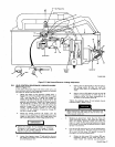
Figure
6-1.
Engine
Controls
Page
12