


B.
Welding
Cables
If
welding
cables
were
not
ordered
with
this
unit,
the
steps
listed
should
be
followed
to
ensure
the
best
welding
performance:
1.
It
is
recommended
that
the
welding
cables
be
kept
as
short
as
possible,
be
placed
close
together,
and
be
of
adequate
current
carrying
capacity.
The
resistance
of
the
welding
cables
and
connections
causes
a
voltage
drop
which
is
added
to
the
voltage
of
the
arc.
Excessive
cable
resistance
may
result
in
overloading
as
well
as
reducing
the
maximum
current
output
capability
of
this
unit.
Proper
operation
is
to
a
great
extent
dependent
on
the
use
of
welding
cables
and
connections
that
are
in
good
condition
and
of
adequate
size.
An
insulated
electrode
holder
must
be
used
to
ensure
the
operators
safety.
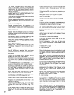
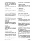
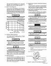
2.
Use
Table
3-1
as
a
guide
for
selecting
correct
cable
size
for
the
anticipated
maximum
weld
current
which
will
be
used.
Table
3-1
shows
total
cable
length,
which
includes
the
electrode
and
work
cable.
Example:
If
the
electrode
holder
cable
is
75
feet
long
and
the
work
cable
is
25
feet
long,
select
the
size
cable
that
is
recommended
for
100
feet
at
the
maximum
weld
current
that
is
to
be
used.
3.
Do
not
use
damaged
or
frayed
cables.
4.
Follow
the
electrode
holder
manufacturers
instructions
for
installing
the
electrode
holder
onto
the
electrode
cable.
5.
Use
correct
lugs
on
the
weld
cable
to
connect
the
work
clamp
and
to
connect
the
cables
to
the
weld
output
terminals.
Install
the
cables
to
the
output
terminals
according
to
Section
3-2A.
6.
Ensure
that
all
connections
are
clean
and
tight.
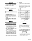
Table
3-1.
Welding
Cable
Size
WELDING
TOTAL
LENGTI-IOF
CABLE
ICOPPE
RI
IN
WELD
CIA
CUlT
AMPERES
50
100
150
200
250
300
350
400
100
4
4
2
2
2
1
1/0
1/0
150
2
2 2
1
1/0
2/0
3/0
3/0
200
1
1
1
1/0
2/0
3/0
4/0
4/0
250
1/0
1/0
1/0
2/0
3/0
4/0
4/0
2-2/0
300
2/0
2/0
2/0
3/0
4/0 4/0
2-2/0
2-3/0
350
3/0
3/0
3/0
4/0
4/0
2~2/O
2-3/0
2-3/0
400
3/0
3/0
3/0
4/0
2-2/0
2-3/0
3-2/0
2-4/0
500
4/0
4/0
4/0
2-2/0
2~3/0
2-3/0
24/0
3-3/0
A-002
702-A
NOTE.
A,
5OFEETOR
LESS.
B.
CABLE
SIZE
IS
BASED
ON
DIRECT
CURRENT
lDCl,
100%
DUTY
CYCLE
AND
EITHER
A
4
VOLTS
OR
LESS
DROP
OR
A
CURRENT
DENSITY
OF
NOT OVER
300
CIRCULAR
MILS
PER
AMP.
C.
WELD
CABLE
INSULATION
WITH
A
VOLTAGE
RATING
TO
WITHSTAND
THE
OPEN-CIRCUIT
VOLT
AGE
(CCV)
OF
THE
WELDING
GENERATOR
MUST
BE
USED.
WHILE
MOST
WELDING
GENERATORS
HAVE
AN
OPEN-CIRCUIT
VOLTAGE
OF
LESS
THAN
100
VOLTS.
SOME
WELDING
GENERATORS
OF
SPECIAL
DESIGN
MAY
HAVE
HIGHER
OPEN-CIRCUIT
VOLTAGE.
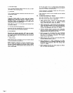
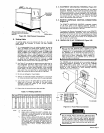
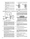
3-
3.
EQUIPMENT
GROUNDING
TERMINAL
(Figure
3-2)
Normally,
engine-driven
Welding
generators
do
not
require
grounding.
However,
since
this
unit
has
auxiliary
power
plant
capability,
grounding
of
the
frame
and
case
may
be
required,
A
grounding
terminal
has
been
provided
on
the
front
panel
for
this
purpose
(see
Figure
3-2).
For
detailed
grounding
instructions
consult
your
local
or
state
codes
or
the
latest
issue
of
the
National
Electrical
Code.
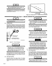
3-4.
REMOTE
AMPERAGE
CONTROL
CONNECTIONS
(Figure
5-1)
The
REMOTE
AMPERAGE
CONTROL
receptacle,
located
on
the
front
panel
of
the
welding
generator
provides
a
junction
point
for
connecting
a
Remote
Amperage
Control
to
the
amperage
control
Circuitry
in
the
unit.
To
Connect
the
Remote
Amperage
Control
to
the
REMOTE
AMPERAGE
CONTROL
receptacle,
insert
the
three-prong
plug
from
the
remote
control
into
the
receptacle
and
rotate
the
plug
as
far
as
it
will
turn
in
clockwise
direction.
Once
fully
rotated,
the
plug
will
be
locked
in
the
receptacle
and
will
not
pull
Out
under
stress.
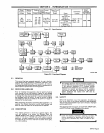
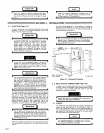
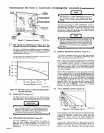
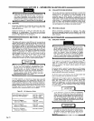
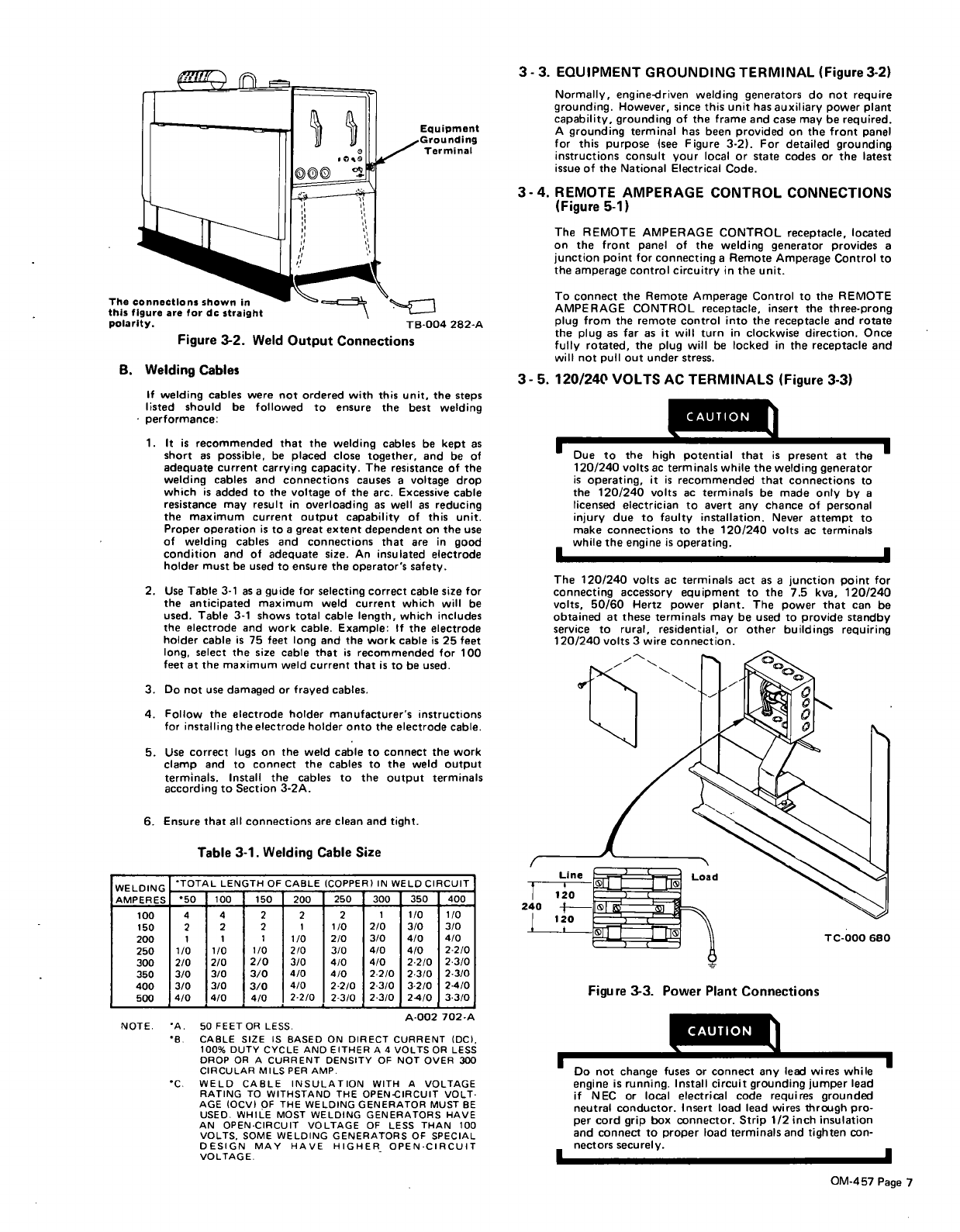
3-5.
120/240
VOLTS
AC
TERMINALS
(Figure
3-3)
the
h
igh
pote
nt
ial
t
hat
is
p
rese
nt at
t
he
120/240
volts
ac
terminals
while
the
welding
generator
is
operating,
it
is
recommended
that
connections
to
the
120/240
volts
ac
terminals
be
made
only
by
a
licensed
electrician
to
avert
any
chance
of
personal
injury
due
to
faulty
installation.
Never
attempt
to
make
connections
to
the
120/240
volts
ac
terminals
while the
engine
is
operating.
The
120/240
volts
ac
terminals
act
as
a
junction
point
for
connecting
accessory
equipment
to
the
7.5
kva,
120/240
volts.
50/60
Hertz
power
plant.
The
power
that
can
be
obtained
at
these
terminals
may
be
used
to
provide
standby
service
to
rural,
residential,
or
other
buildings
requiring
120/240
volts
3
wire
connection.
CAUTION
I
Do
not
change
fuses
or
Connect
any
leed
wires
while
engine
is
running.
Install
Circuit
grounding
jumper
lead
if
NEC
or
local
electrical
code
requires
grounded
neutral
conductor,
Insert
load
lead
wires
through
pro
per
cord
grip
box
connector.
Strip
1/2
inch
insulation
and
connect
to
proper
load
terminals
and
tighten
con
nectors
securely.
The
connections
shown
in
this
figure
are
for
dc
Straight
polarity.
Figure
3-2.
Weld
Output
Connections
TB-004
282-A
Figure
3-3.
Power
Plant
Connections
I
I
.
OM-457
Page
7