


I
I
merit.
IMPORTANT
U
U
NOTE
I
SECTION
3
-
INSTALLATION
3
-
1.
LOCATION
(Figure
3-1)
A
proper
installation
site
should
be
selected
for
the
welding
generator
if
the
unit
is
to
provide
dependable
service,
and
remain
relatively
maintenance
free.
I
F~O~TANT
II
this
welding
generator
is
to
be
mounted
on
a
trailer
(optional),
enture
that
the
engine
end
is
mounted
toward
the
front
(hitch
end)
of
the
trailer
to
maintain
proper
weight
distribution.
Also
ensure
that the
torque
weight
of
the
trailer
is
5
to
10%
of
the
gross
vehicle
weight.
It is
recommended
that
a
properly
fitting
canvas
cover
(optional)
be
placed
over
the
welding
generator
when
not
in
operation
to
protect
the
unit
from
the
environment.
L
CAUTION
U
If
this
unit
is
to
be
operated
indoors,
it
should
be
located
in
a
place
where
the
exhaust
fumes
from
the
engine
can
be
vented
out
of
the
building.
Failure
to
comply
with
proper
venting
may
result
in
stjrious
bodily
injury
or
loss
of
life.
;~=ANT;
I
The
engine
exhaust
system
on
this
welding
generator
has
not
been
equipped
with
a
spark
arrestor
unless
it
was
specifically
ordered
as
an
optional
accessory.
A
spark
arrestor,
maintained
in
effective
working
order,
is
mandatory
if
this
welding
generator
is
to
be
operated
in
a
National
Forest,
or
on
California
Grasslands,
brush,
or
forest
covered
land
(see
Section
4442
of
California
Public
Resources
Code).
For
other
areas,
check
your
state
and
local
laws.
A
proper
installation
site
permits
freedom
of
air
movement
into
and
out
of
the
welding
generator,
and
also
least
subjects
the
unit
to
dust,
dirt,
moisture,
and
corrosive
vapors.
A
minimum
of
18
inches
of
unrestricted
space
must
be
maintained
between
the
welding
generator
front
and
rear
panels
and
the
nearest
obstruction.
Also,
the
underside
of
the
welding
generator
muss
be
kept
completely
free
of
ob
structions.
The
installation
site
should
also
permit
easy
removal
of
the
outer
enclosure
for
maintenance
functions.
Do
not
place
any
filtering
device
over
the
intake
air
passages
of
the
welding
generator
as
this
would
restrict
the
volume
of
intake
air
and
thereby
subject
the
internal
components
to
an
overheating
condition
and
subsequent
failure.
Warranty
is
void
if
any
type
of
filtering
device
is
used.
On
most
welding
generators
a
lifting
device
is
provided
for
moving
the
unit.
However,
if
a
fork
lift
vehicle
is
used
for
lifting
the
unit,
be
sure
that
the
lift
forks
are
long
enough
to
extend
completely
under
base.
of
lift
f
short
e
xte
nd
o
ut
of
the
opposite
side
of
the
base
will
expose
internal
compon
ents
to
damage
should
the
tips
of
the
lift
forks
pene
trate
the
bottom
of
the
unit.
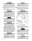
3-2.
WELD
OUTPUT
CONNECTIONS
(Figure
3-2)
To
obtain
the
full
rated
output
from
this
unit,
isis
necessary
to
select,
install,
and
maintain
proper
welding
cables.
Failure
to
comply
in
any
of
these
areas
may
result
in
less
than
satisfactory
welding
performance.
Ensure
that
the
unit
is
completely
~own
before
~iaking
any
weld
output
connections.
1
A.
Location
The
POSITIVE
and
NEGATIVE
weld
output
terminals
are
located
on
the
lower
portion
of
the
front
panel.
Open
the
lower
front
access
door.
Route
the
weld
cables
between
the
two
horizontal
pieces
of
angle
iron
on
the
front
of
the
base
(see
Figure
3-2)
and
connect
the
cables
to
the
weld
output
terminals.
Secure
the
lower
access
door.
Under
this
heading,
installation,
operating,
and
main
tenance
procedures
or
practices
will
be
found
that
if
not
carefully
followed
nay
result
in
damage
to
equip-
Under
this
heading,
explanatory
statements
will
be
found
that
need
special
emphasis
to
obtain
the
most
efficientoperation
of
the
equipmrrnt.
I
I
I
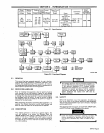
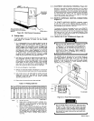
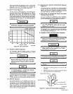
Figure
3-1.
Dimensional
Drawing
TA-004
285
U
U
I
I
Holes
are
provided
in
the
base
for
mounting
purposes.
Figure
3-1
gives
overall
dimensions
and
the
base
mounting
hole
layout.
NOTE
If
the
welding
generator
is
equipped
with
a
POLAR
ITY
SWITCH
(Optional),
the
weld
output
terminals
i
are
labeled
ELECTRODE
and
WORK.
1
Page
6